FX3U Series Programmable Controllers
User’s Manual - Hardware Edition
385
19 FX3U-7DM (Display Module)
19.19 User (User-Registered Device Setting)
11
High-Speed
Counters
12
Output Wiring
13
Wiring for
Various Uses
14
Test Run,
Maintenance,
Troubleshooting
15
IInput/Output
Powered
Extension Units
16
Input/Output
Extension
Blocks
17
Extension
Power Supply
Unit
18
Other Extension
Units and
Options
19
Display Module
20
Terminal Block
19.19 User (User-Registered Device Setting)
The procedure for specifying the devices which display as "User" at the "Monitor/Test" menu is explained
below. The user-registered devices are specified by writing the "device type" and "device No." at "D to
D+7" in the system information (system signal 1).
→ Refer to Section 19.8 for operation.
→ Refer to Section 19.18 for system information setting.
→ Refer to Subsection 19.19.3 to 19.19.5 for program examples.
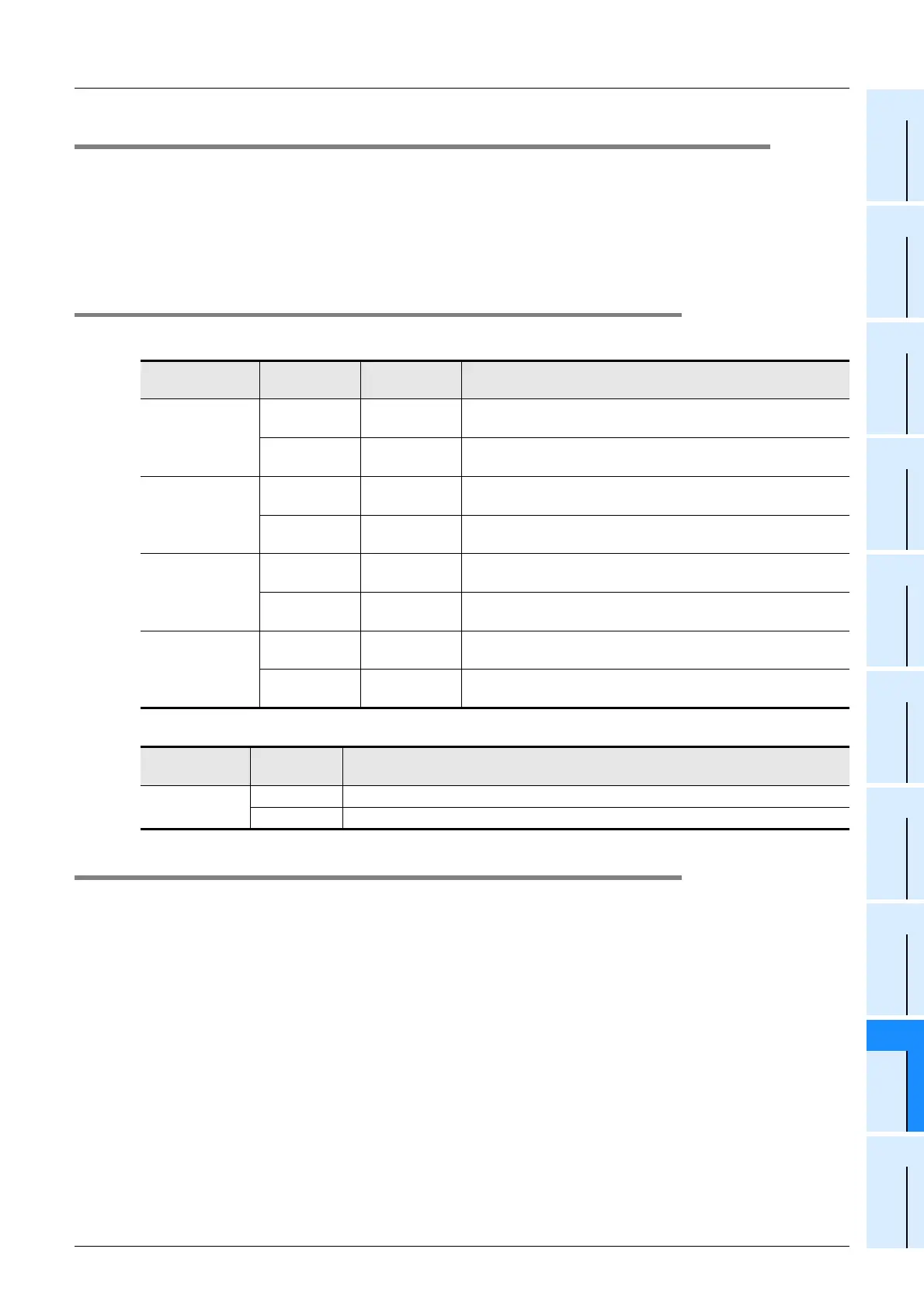
19.19.1 System information - user-registered device setting
1. System signal 1
2. System signal 2
19.19.2 Precaution when setting 3 or fewer devices
When 3 or fewer devices are set as user-registered devices, the "type" setting for unused devices should be
set to a value other than 7 and 8.
→ Refer to Subsection 19.19.4 for a program example.
User-Registered
Device No.
System
Information
Description Setting Value
1
D Device type
D= K7: Data register [D] (16-bit)
D= K8: Data register [D] (32-bit)
D+1 Device No.
When D = K7, D + 1 = K0 to K8511
When D = K8, D + 1 = K0 to K7998, K8000 to K8510
2
D+2 Device type
D+2= K7: Data register [D] (16-bit)
D+2= K8: Data register [D] (32-bit)
D+3 Device No.
When D = K7, D + 3 = K0 to K8511
When D = K8, D + 3 = K0 to K7998, K8000 to K8510
3
D+4 Device type
D+4= K7: Data register [D] (16-bit)
D+4= K8: Data register [D] (32-bit)
D+5 Device No.
When D = K7, D + 5 = K0 to K8511
When D = K8, D + 5 = K0 to K7998, K8000 to K8510
4
D+6 Device type
D+6= K7: Data register [D] (16-bit)
D+6= K8: Data register [D] (32-bit)
D+7 Device No.
When D = K7, D + 7 = K0 to K8511
When D = K8, D + 7 = K0 to K7998, K8000 to K8510
System
Information
Setting
Content
Display Screen Status
M+6
ON "User-registered device" screen, or "user message" screen is displayed.
OFF Other screen is displayed.

 Loading...


