FX3U Series Programmable Controllers
User’s Manual - Hardware Edition
137
8 Installation In Enclosure
8.6 Procedures for Installing Directly (with M4 Screws)
1
Introduction
2
Features and
Part Names
3
Product
Introduction
4
Specifications
5
Version and
Peripheral
Devices
6
System
Configuration
7
Input/Output
Nos., Unit Nos.
8
Installation
9
Preparation and
Power Supply
Wiring
10
Input Wiring
8.6 Procedures for Installing Directly (with M4 Screws)
The product can be installed directly in the enclosure (with screws).
Point
Position the holes so that there is a gap of 1 to 2 mm (0.04" to 0.08") between the products.
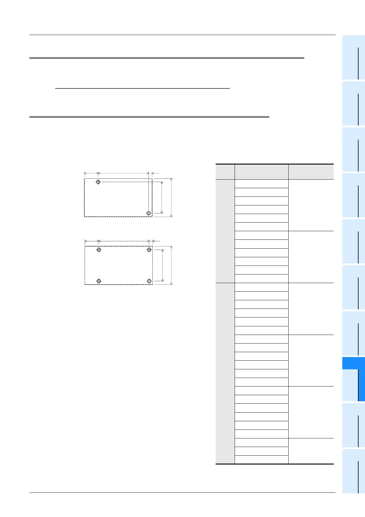
8.6.1 Hole pitches for direct mounting
The product mounting hole pitches are shown below.
For the pitch that varies depending on the product, refer to the table.
1. Main unit (A or B)
Unit: mm (inches)
Model name
Mounting hole
pitch (W)
A
FX
3U-16MR/ES
103 (4.06")
FX
3U-16MT/ES
FX
3U-16MT/ESS
FX
3U-16MR/DS
FX
3U-16MT/DS
FX
3U-16MT/DSS
FX
3U-32MR/ES
123 (4.85")
FX
3U-32MT/ES
FX
3U-32MT/ESS
FX
3U-32MR/DS
FX
3U-32MT/DS
FX
3U-32MT/DSS
B
FX
3U-48MR/ES
155 (6.11")
FX
3U-48MT/ES
FX
3U-48MT/ESS
FX
3U-48MR/DS
FX
3U-48MT/DS
FX
3U-48MT/DSS
FX
3U-64MR/ES
193 (7.6")
FX
3U-64MT/ES
FX
3U-64MT/ESS
FX
3U-64MR/DS
FX
3U-64MT/DS
FX
3U-64MT/DSS
FX
3U-80MR/ES
258 (10.16")
FX
3U-80MT/ES
FX
3U-80MT/ESS
FX
3U-80MR/DS
FX
3U-80MT/DS
FX
3U-80MT/DSS
FX
3U-128MR/ES
323 (12.72")FX
3U-128MT/ES
FX
3U-128MT/ESS
W
22
(0.87")
A
5
(0.2")
80 (3.15")
90 (3.55")
W
22
(0.87")
B
5
(0.2")
80 (3.15")
90 (3.55")

 Loading...


