FX3U Series Programmable Controllers
User’s Manual - Hardware Edition
435
21 FX3U-FLROM-16/64/64L (Memory Cassette)
21.5 Memory Cassette <-> PLC (RAM Memory) Transfers by Loader Function
21
Memory
Cassette
22
Battery
A
Special Devices
(M8000-,D8000-)
B
Instruction List
C
Character-code
D
Discontinued
models
21.5 Memory Cassette
<−>
PLC (RAM Memory) Transfers by Loader Function
The FX3U-FLROM-64L loader function ([WR] and [RD] key operation) is explained in this section.
• Program transfers (reading/writing) are possible between the memory cassette and the PLC’s internal
RAM memory.
• The loader function is enabled while the PLC is stopped.
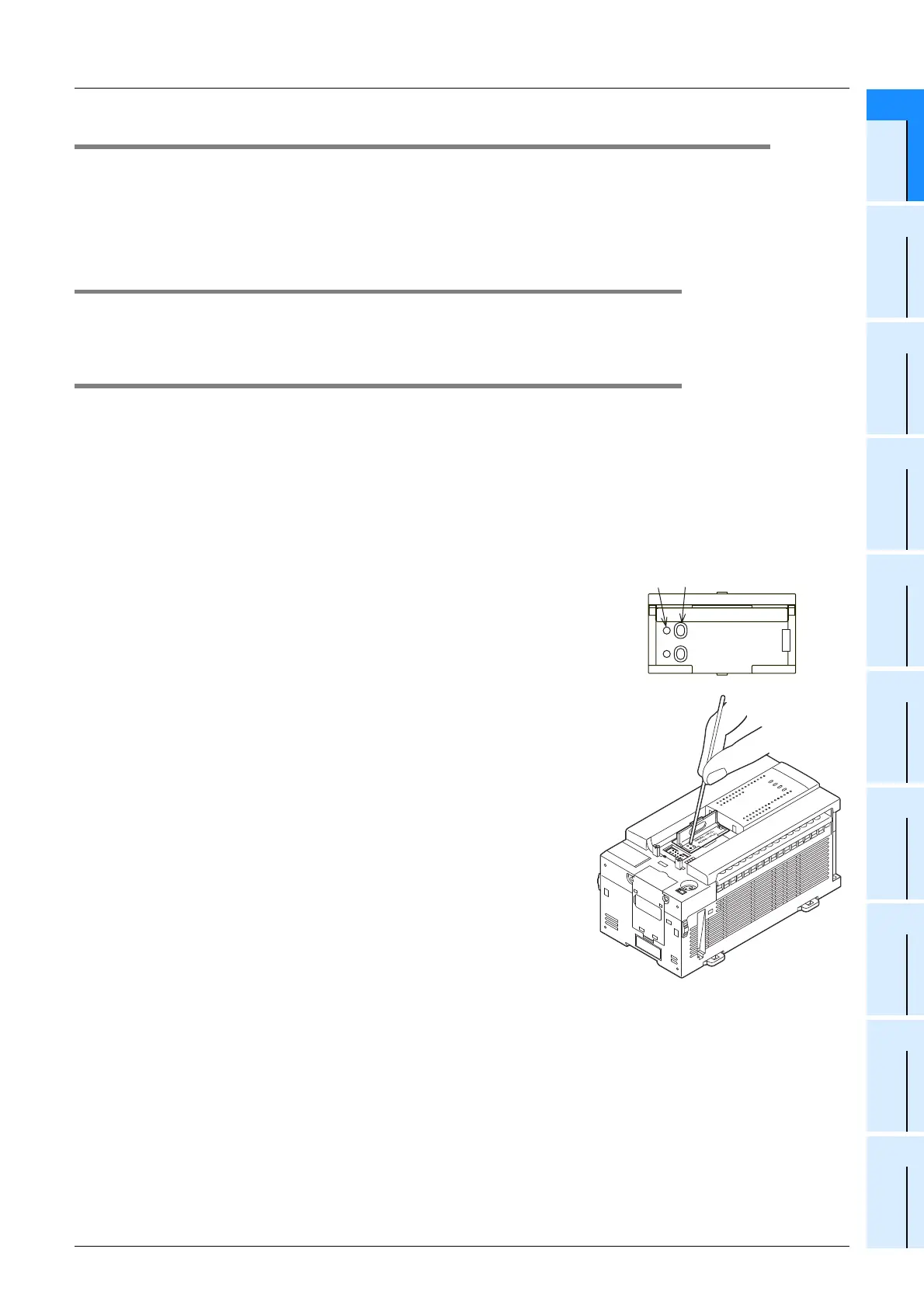
21.5.1 Tool for pressing the [WR] and [RD] keys
Use an insulator tool (plastic, ceramic, etc.) to press the [WR] and [RD] keys. The area around the keys is not
insulated. Using a metal screwdriver, etc can cause equipment damage.
21.5.2 Writing (WR: 64L −> PLC)
A memory cassette program is written to the PLC’s internal RAM memory.
Required condition: The PLC must be stopped.
1 Install the memory cassette on the main unit.
(Setting the PROTECT switch to ON (on memory cassette’s rear face) prevents accidental overwriting of
memory cassette program.)
→ Refer to Subsection 21.2.1 for the installation procedure.
• Verify that the PLC power is OFF, then install the memory cassette on the PLC.
• Turn the PLC power ON.
• Raise the memory cassette’s eject lever.
2 Press the [WR] key 1 time.
The [WR] LED lights, and a preparation status is established.
• To cancel, press the [RD] key.
3 Press the [WR] key again.
Writing is executed, and the [WR] LED goes off.
• Writing to the built-in RAM is completed instantaneously, and the
LED goes out soon.
4
Remove the memory cassette from the main unit.
Writing is completed when the [WR] LED goes off.
After turning the PLC power OFF, remove the memory cas-
sette from the PLC.
→ Refer to Subsection 21.2.2 for the removal procedure.
RUN
STOP
FX
3U
-48MR/ES
ERROR
RUN
BATT
POWER
0
312
IN
645
21
7
20
24
22
23
26
25
10
11 1312
1614
15
17
27
OUT
0
3
1
2
6
4
5
21
7
20
24
22
23 26
25
10
11
13
12
16
14
15
17
27
[WR] LED [WR] key
WR(64LJPLC)
RD(64LIPLC)

 Loading...


