276
FX3U Series Programmable Controllers
User’s Manual - Hardware Edition
15 FX2N-32/48E*-* (Input/Output Powered Extension Units)
15.5 FX2N-32ER, FX2N-48ER, FX2N-48ER-D
3. Output specifications (relay output type)
15.5.2 External dimensions
FX2N-32ER
Item FX2N-32ER FX2N-48ER, FX2N-48ER-D
Number of output points 16 points 24 points
Connection type Removable terminal block (M3 screw)
Output unit Relay
External power supply 250V AC/30V DC or less
Output circuit insulation Mechanical insulation
Indication of output operation When power is applied to relay coil, LED on panel is lit.
Max. load
Resistance
load
2 A/point
The total load current per common ter-
minal should be the following value.
• 8 output points/common terminal: 8 A
or less
2 A/point
The total load current per common ter-
minal should be the following value.
• 4 output points/common terminal: 8 A
or less
• 8 output points/common terminal: 8 A
or less
Inductive load
80 VA
→ For the product life, refer to Subsection 4.4.2.
→ For cautions on external wiring, refer to Subsection 12.2.4.
Open circuit leakage current −
Min. load 5V DC, 2 mA (reference value)
Response time
OFF→ON Approx. 10 ms
ON→OFF Approx. 10 ms
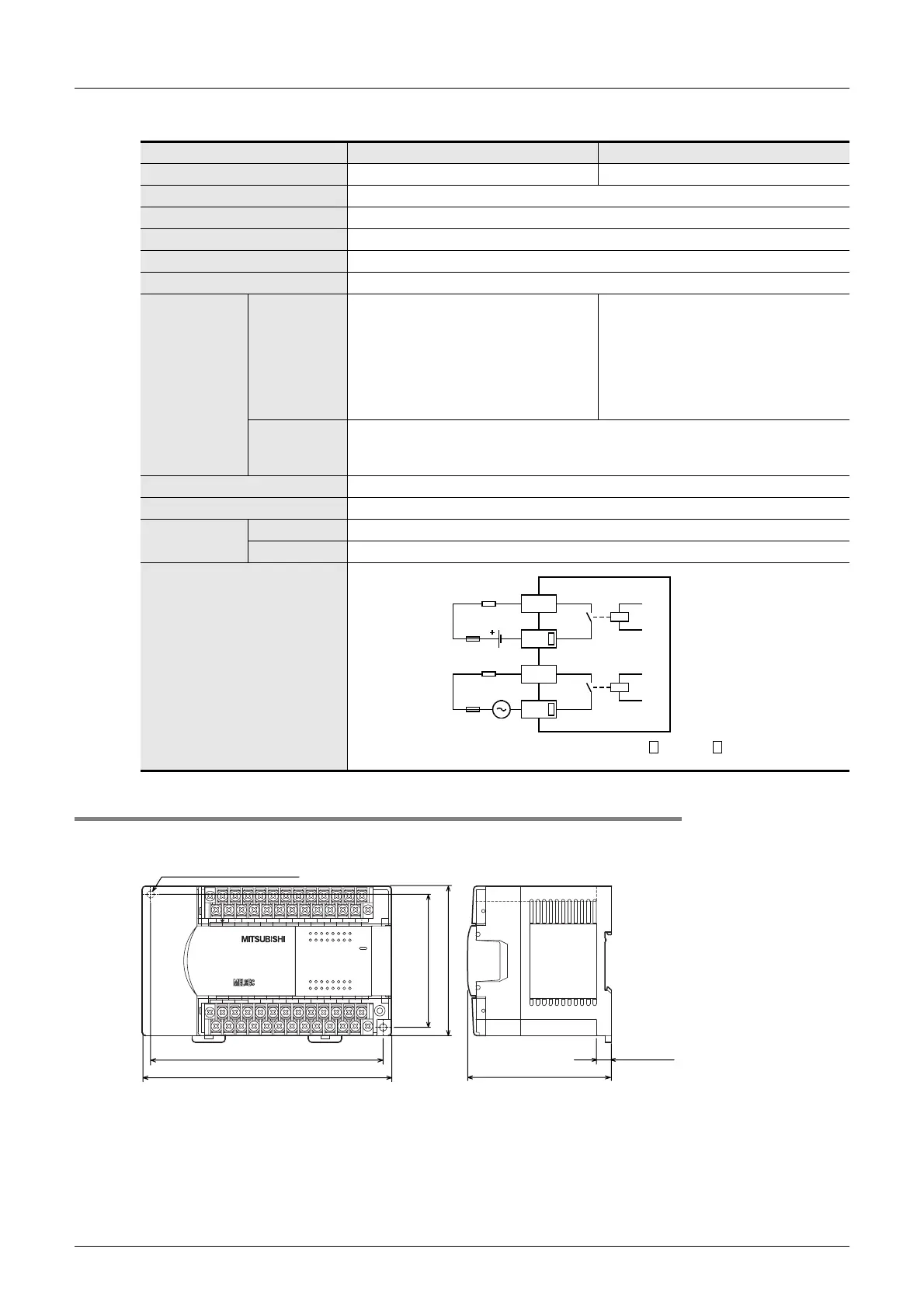
Output circuit diagram
External
power supply
Load
Fuse
Y
COM
DC power
supply
Fuse
Y
COM
A common number applies to the of [COM ].
72456
1
3
0
72456
1
3
0
OUT
IN
L
X1
X3 X5 X7
X6
X0
X2 X4 X6
24+
N
COM X4
X7
COM4COM2
Y4
Y5
Y6
Y7 COM3
Y0
Y1
Y2
Y3
COM1
Y0
Y1
Y2
Y3
Y4
Y5
Y6
Y7
X3
X2
X1
X0
X5
FX
2N
-32ER
POWER
72456
1
3
0
72456
1
3
0
150 (5.91")
140 (5.52") (mounting hole pitch)
80 (3.15")
(mounting hole pitch)
90 (3.55")
9 (0.36")
Unit : mm (inches)
87 (3.43")
2-φ4.5 mounting holes
The terminal block uses
M3 terminal screws.

 Loading...


