FX3U Series Programmable Controllers
User’s Manual - Hardware Edition
241
14 Test Operation, Adjustment, Maintenance and Troubleshooting
14.1 Preparation for Test Operation
11
High-Speed
Counters
12
Output Wiring
13
Wiring for
Various Uses
14
Test Run,
Maintenance,
Troubleshooting
15
IInput/Output
Powered
Extension Units
16
Input/Output
Extension
Blocks
17
Extension
Power Supply
Unit
18
Other Extension
Units and
Options
19
Display Module
20
Terminal Block
14.1 Preparation for Test Operation
14.1.1 Preliminary inspection [power OFF]
Incorrect connection of the power supply terminal, contact of the DC input wire and power supply wire, or
short-circuiting of output wires may result in serious damage.
Before applying power, check that the power supply and ground terminals are connected correctly and input/
output devices are wired properly.
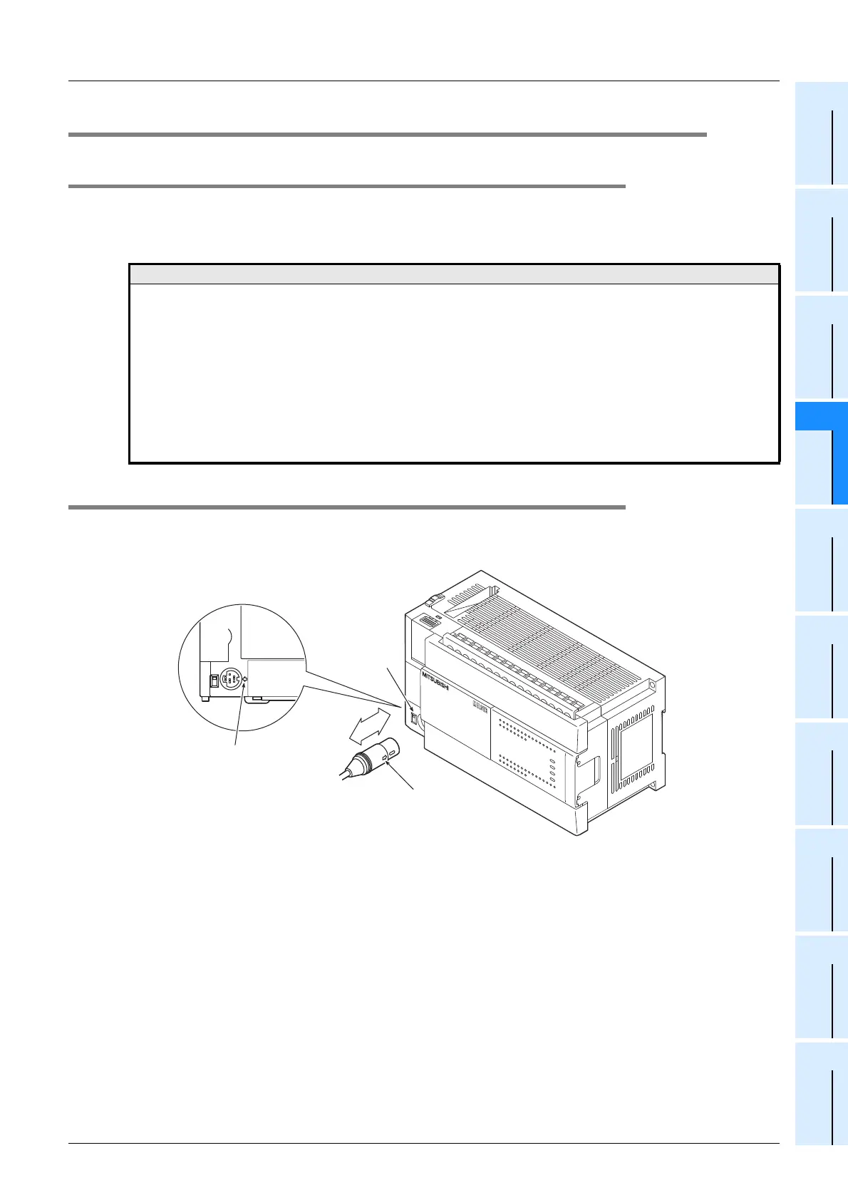
14.1.2 Connection to built-in programming connector
When connecting the communication cable of a peripheral device, align the positioning mark of the cable with
that of the main unit.
Notes
The dielectric withstand voltage and insulation resistance test of the PLC should be measured in accordance with the
following procedures.
1) Remove all input/output wires and power supply wires from the PLC.
2) Connect a crossing wire to each of the PLC terminals (power supply terminal, input terminals and output
terminals) except the ground terminal.
For the dielectric withstand voltage test of each terminal, refer to the generic specifications for the product.
→ Refer to Section 4.1.
3) Measure the dielectric withstand voltage and insulation resistance between each terminal and the ground
terminal.
Dielectric withstand voltage: 1.5kV AC or 500V for 1min (The terminals vary in dielectric withstand voltage.)
Insulation resistance: 500V DC / 5MΩ or more
FX
3U
-48MFX
3U
RUN
POWER
ERROR
BATT
FX
3U
-48MFX
3U
ERROR
RUN
BATT
POWER
031
2
IN
OUT
645
21
7
20
24
22
23
26
25
10 11 13
12 1614
15
17
27
0312
64
5
21
7
20
24
22
23
26
25
10
11
13
12
1614
15
17
27
Positioning
mark
Positioning mark
Programming
connector
Communication cable

 Loading...


