FX3U Series Programmable Controllers
User’s Manual - Hardware Edition
255
14 Test Operation, Adjustment, Maintenance and Troubleshooting
14.6 Judgment by Error Codes and Representation of Error Codes
11
High-Speed
Counters
12
Output Wiring
13
Wiring for
Various Uses
14
Test Run,
Maintenance,
Troubleshooting
15
IInput/Output
Powered
Extension Units
16
Input/Output
Extension
Blocks
17
Extension
Power Supply
Unit
18
Other Extension
Units and
Options
19
Display Module
20
Terminal Block
14.6.4 Error Code List and Action
When a program error occurs in the PLC, the error code is stored in special data registers D8060 - D8067 and
D8438. The following actions should be followed for diagnostic errors.
Error codes in shaded columns are added in FX3U PLCs.
Error
code
PLC operation at
error occurrence
Contents of error Action
I/O configuration error [M8060(D8060)]
Ex-
ample:
1020
Continues
operation
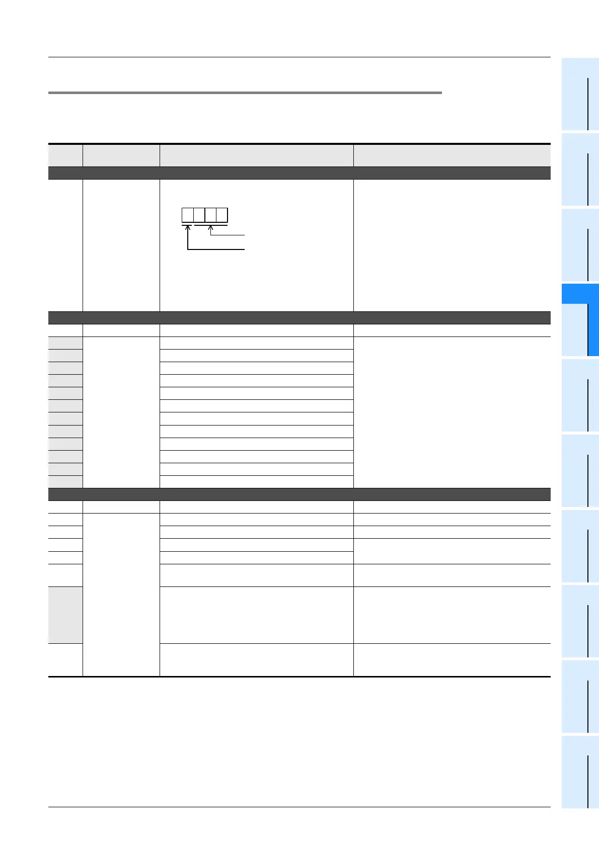
The head number of unconnected I/O device
• 1st to 3rd digits: Device number
• 4th digit: I/O type
(1 = input (X), 0 = output (Y))
Example: When 1020 is stored in D8060
Inputs X020 and later are unconnected.
Unconnected I/O relay numbers are programmed.
The PLC continues its operation. Modify the
program, check wiring connection, or add the
appropriate unit/block.
Serial communication error 2 [M8438 (D8438)]
0000 ⎯ No error
3801
Continues
operation
Parity, overrun or framing error
• Inverter communication, computer link and
programming:
Ensure the communication parameters are
correctly set according to their applications.
• N:N network, parallel link, etc.:
Check programs according to the applications.
• Remote maintenance:
Ensure modem power is ON and check the
settings of the AT commands.
• Wiring:
Check the communication cables for correct
wiring.
3802 Communication character error
3803 Communication data sum check error
3804 Communication data format error
3805 Command error
3806 Communication time-out detected
3807 Modem initialization error
3808 N:N network parameter error
3812 Parallel link character error
3813 Parallel link sum error
3814 Parallel link format error
3820 Inverter communication error
PLC hardware error [M8061(D8061)]
0000 ⎯ No error
6101
Stops
operation
RAM error
6102 Operation circuit error
6103 I/O bus error (M8069 = ON)
Check for the correct connection of extension
cables.
6104 Powered extension unit 24 V failure (M8069 = ON)
6105 Watchdog timer error
Check user program.
The scan time exceeds the value stored in D8000.
6106 I/O table creation error (CPU error)
When turning the power ON to the main unit, a
24V power failure occurs in a powered extension
unit. (The error occurs if the 24V power is not
supplied for 10 seconds or more after the main
power is turned ON.)
6107 System configuration error
Check the number of the connected special function
units/blocks. For a few special function units/blocks,
the connectable number is limited.
1 0 2 0
1: Input (X), 0: Output (Y)
Device number: 10 to 337
Example: When X020 is unconnected
BCD conversion value

 Loading...


