FX3U Series Programmable Controllers
User’s Manual - Hardware Edition
139
8 Installation In Enclosure
8.6 Procedures for Installing Directly (with M4 Screws)
1
Introduction
2
Features and
Part Names
3
Product
Introduction
4
Specifications
5
Version and
Peripheral
Devices
6
System
Configuration
7
Input/Output
Nos., Unit Nos.
8
Installation
9
Preparation and
Power Supply
Wiring
10
Input Wiring
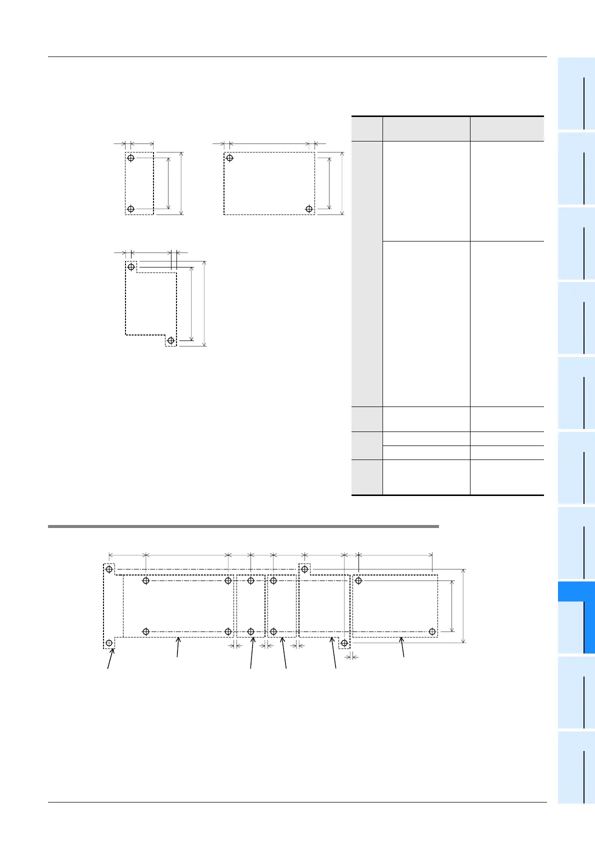
5. Special function unit/block (H, I or J)
8.6.2 Example of mounting hole pitches
Unit: mm (inches)
Model name
Mounting hole
pitch(W)
H
FX
0N-3A
FX
2N-2AD
FX
2N-2DA
FX
2N-1PG
FX
2N-1PG-E
FX
2N-10PG
FX
2N-64CL-M
FX
2N-32CCL
FX
2N-16LNK-M
39 (1.54")
FX
3U-4AD
FX
3U-4DA
FX
3U-20SSC-H
FX
3U-1PSU-5V
FX
2N-4AD
FX
2N-4DA
FX
2N-4AD-PT
FX
2N-4AD-TC
FX
2N-5A
FX
2N-2LC
FX
2N-1HC
FX
2N-1RM-SET
FX
2N-1RM-E-SET
FX
2N-232IF
FX
2N-32ASI-M
51 (2.01")
IFX2N-16CCL-M
Refer to the
figure shown left.
J
FX
2N-8AD 67 (2’64")
FX
2N-20PSU 52 (2’05")
−
FX
2N-10GM
FX
2N-20GM
These units can-
not be installed
directly.
J
98 (3.86")
4
(0.16")
4
(0.16")
W
105 (4.14")
I
75
(2.96")
4
(0.16")
4
(0.16")
80 (3.15")
90 (3.55")
4
(0.16")
W
80 (3.15")
H
90 (3.55")
155 (6.11")
GH J
27
(1.07")
26
(1.03")
45
(1.78")
67
(2.64")
140 (5.52")
* The gap between products is 2 mm (0.08").
98 (3.86")
37.1
(1.47")
80 (3.15")
B
11
(0.44")
2 * (0.08")
FX
2N
-32ER-ES/UL
2 *
(0.08")
2 *
(0.08")
FX
2N
-8ADFX
2N
-2ADFX
2N
-16EX-ES/UL
CD
FX
3U
-232ADP
Unit:mm (inches)
FX
3U
-48MR/ES
2 *
(0.08")

 Loading...


