FX3U Series Programmable Controllers
User’s Manual - Hardware Edition
180
10 Input Wiring Procedures (Input Interruption and Pulse Catch)
10.4 Input Interruption (I00
to I50
) - With Delay Function
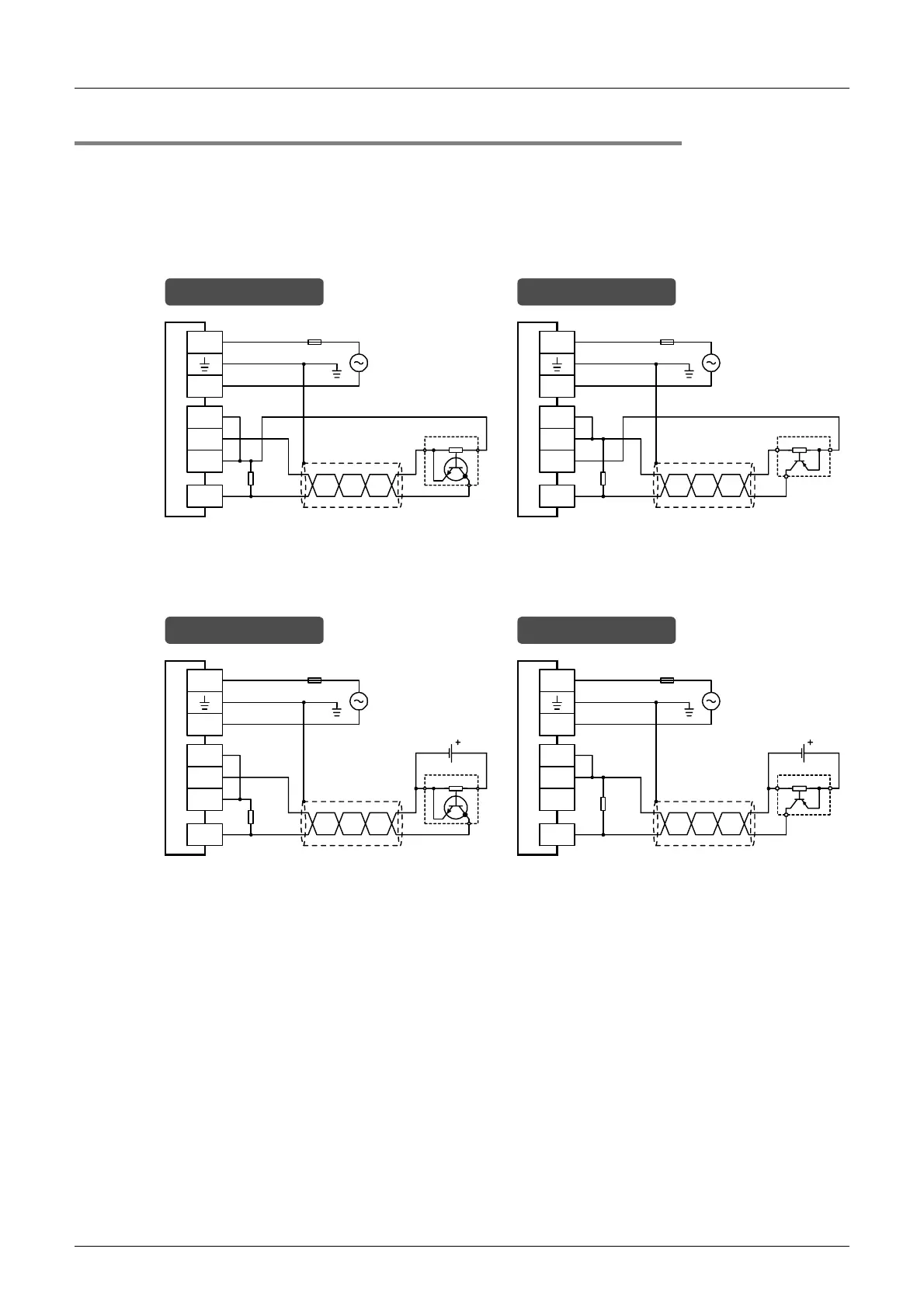
10.4.4 Examples of external wiring
Use shielded twisted-pair cables for connecting cables.
Ground the shield of each shielded cable only on the PLC side.
1. Examples of input interruption (I000 or I001) wiring using X000
When another input terminal is used, wire it according to the following diagrams.
1) When 24V DC service power supply is used
2) When 24V DC external power supply is used
S/S
L
N
24V
Class D grounding *
Fuse
Sink wiring
0V
X000
Three-wire
1.5
k
Ω
S/S
L
N
24V
Fuse
Source wiring
0V
X000
Three-
wire
1.5
k
Ω
* The grounding resistance should be 100
Ω
or less.
Class D grounding *
S/S
L
N
24V
Fuse
24V DC
Sink wiring
0V
X000
1.5
k
Ω
S/S
L
N
24V
Fuse
24V DC
Source wiring
0V
X000
Three-
wire
1.5
k
Ω
Three-wire
* The grounding resistance should be 100
Ω
or less.
Class D grounding * Class D grounding *

 Loading...


