FX3U Series Programmable Controllers
User’s Manual - Hardware Edition
153
9 Preparation for Wiring and Power Supply Wiring Procedures
9.2 Cable Connecting Procedures
1
Introduction
2
Features and
Part Names
3
Product
Introduction
4
Specifications
5
Version and
Peripheral
Devices
6
System
Configuration
7
Input/Output
Nos., Unit Nos.
8
Installation
9
Preparation and
Power Supply
Wiring
10
Input Wiring
4) Certified connectors (commercially available connectors)
Connectors made by DDK Ltd. shown in Item (3) described in the previous page and connectors made by
Matsushita Electric Works, Ltd. shown in the following table
9.2.3 Terminal block (for europe) [expansion board and special adapters]
The expansion board and special adapters of a terminal block type have terminal blocks for Europe.
1. Applicable products
2. Electric wires
Compliant electric wires and tightening torque
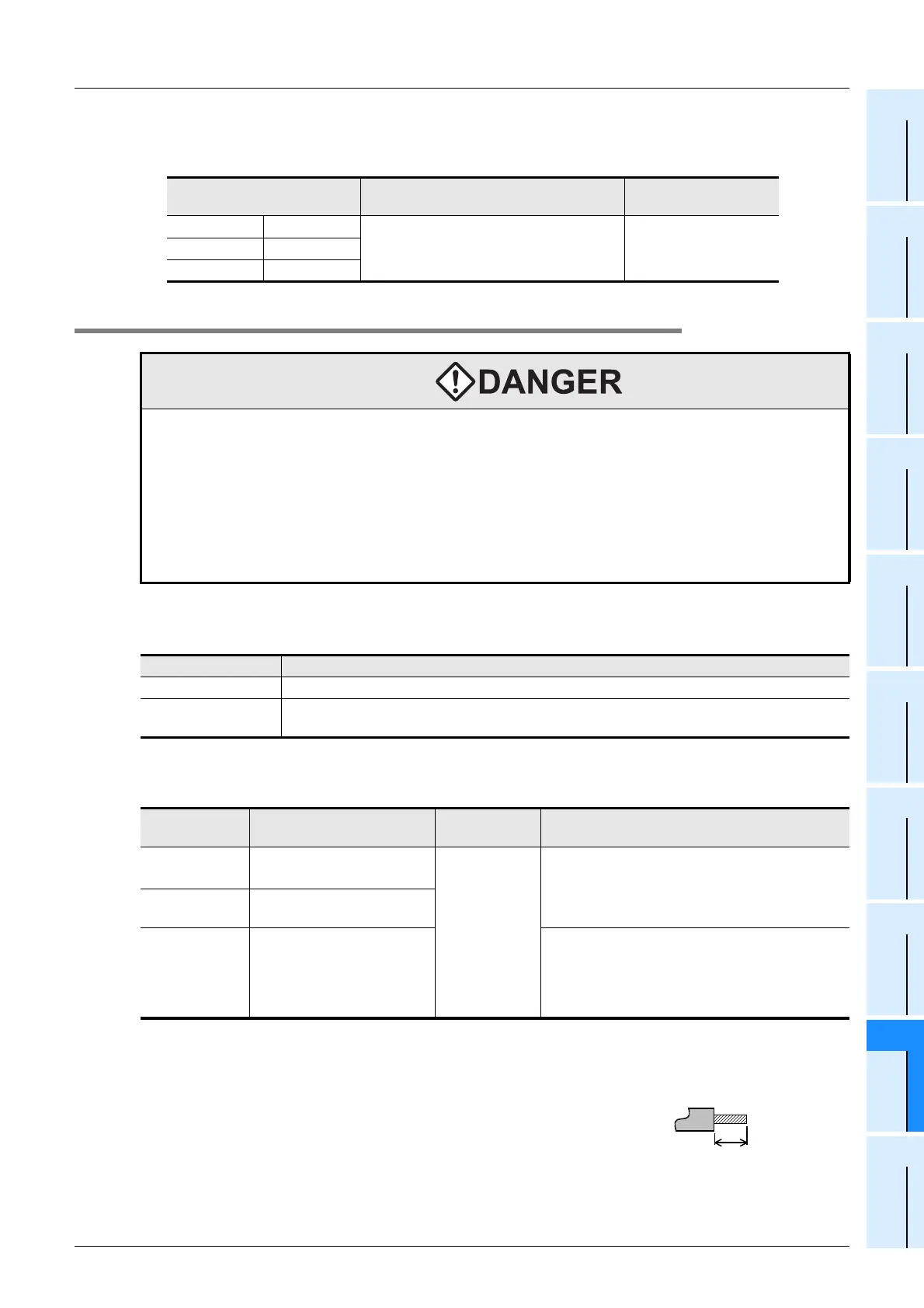
3. Treatment of electric wire ends
Treat the ends of stranded wires and solid wires without coating or using bar terminals with insulating sleeve.
• Treatment of stranded wires and solid wires without coating
- Twist the ends of stranded wires tightly so that loose wires will not
stick out.
- Do not solder-plate the electric wire ends.
Model name of connector
Compliant electric wires
(UL-1061 is recommended)
Pressure bonding tool
Housing AXW1204A
AWG22 (0.3mm
2
)
AWG24 (0.2mm
2
)
AXY52000Contact AXW7221
Semi-cover AXW62001A
WIRING PRECAUTIONS
• Cut off all phases of the power source externally before installation or wiring work in order to avoid electric shock
or damage of product.
• Observe the following items to wire the lines to the European terminal board. Ignorance of the following items may
cause electric shock, short circuit, disconnection, or damage of the product.
- The disposal size of the cable end should follow the dimensions described in this manual.
- Tightening torque should be between 0.22 to 0.25 N
•
m.
- Twist the end of strand wire and make sure there is no loose wires.
- Do not solder-plate the electric wire ends.
- Do not connect electric wires of unspecified size or beyond the specified number of electric wires.
- Fix the electric wires so that the terminal block and connected parts of electric wires are not directly stressed.
Classification Model names
Expansion Board FX
3U-485-BD
Special Adapters
FX
3U-485ADP, FX3U-4AD-ADP, FX3U-4DA-ADP, FX3U-4AD-PT-ADP, FX3U-4AD-TC-ADP,
FX
3U-4HSX-ADP, FX3U-2HSY-ADP
Electric wire size
(stranded wire/solid wire)
Tightening
torque
End treatment
One electric wire
0.3mm
2
to 0.5mm
2
(AWG22 to 20)
0.22 to 0.25N•m
• Remove the coating of the stranded wire, twist
the core wires, and connect the wires directly.
• Remove the coating from the solid wire, and
connect the wire directly.
Two electric
wires
0.3mm
2
(AWG22)
Bar terminal with
insulating sleeve
0.3 mm
2
to 0.5 mm
2
(AWG22 to 20)
(Refer to the following outline
drawing of bar terminal.)
• Bar terminal with insulating sleeve
(recommended product)
AI 0.5-8WH (Phoenix Contact)
• Caulking tool
CRIMPFOX UD6 (Phoenix Contact)
9mm
(0.36")
•
Stranded wire/solid wire

 Loading...


