FX3U Series Programmable Controllers
User’s Manual - Hardware Edition
383
19 FX3U-7DM (Display Module)
19.18 System Information (Restrictions From PLC)
11
High-Speed
Counters
12
Output Wiring
13
Wiring for
Various Uses
14
Test Run,
Maintenance,
Troubleshooting
15
IInput/Output
Powered
Extension Units
16
Input/Output
Extension
Blocks
17
Extension
Power Supply
Unit
18
Other Extension
Units and
Options
19
Display Module
20
Terminal Block
19.18 System Information (Restrictions From PLC)
Some of the display module functions require system information settings in order to enable program control
of these functions. Functions which require the use of system information are listed below.
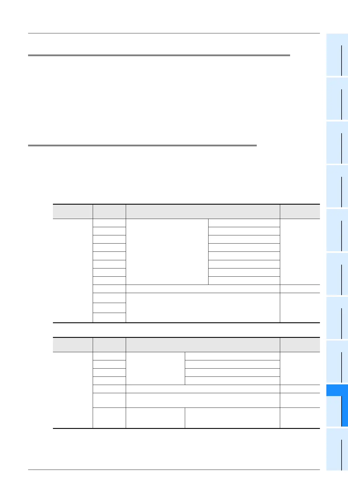
19.18.1 System information list
Special data register D8300 and D8301 devices with first numbers specified are assigned as system
information devices (data register, auxiliary relay). The data register (excluding special data register) should
be specified at the system information’s "system signal 1", and the auxiliary relay (excluding special auxiliary
relay) should be specified at the system information’s "system signal 2". Both D8300 and D8301 have default
settings of "-1".
→ Refer to Section 19.19 to 19.23 for explanations of each system signal.
1. System signal 1
2. System signal 2
• Monitor/test function
- For hexadecimal display of current value:
→ Refer to Section 19.21 for the setting
procedure.
- To use user-registered devices:
→ Refer to Section 19.19 for the setting
procedure.
• Display screen protect function
→ Refer to Section 19.22 for details.
• Operation button ON/OFF information
→ Refer to Section 19.20 for details.
• User message display function
→ Refer to Section 19.23 for details.
Special data
register
System
Information
Description Reference
D8300 = K
Occupies 41
points
D
Devices for user-registered device
settings
Only data registers can be
specified for user-registered
devices.
User-registered device 1 type
Section 19.19
D+1 User-registered device 1 No.
D+2 User-registered device 2 type
D+3 User-registered device 2 No.
D+4 User-registered device 3 type
D+5 User-registered device 3 No.
D+6 User-registered device 4 type
D+7 User-registered device 4 No.
D+8 Device for display screen protect function Section 19.22
D+9
Device where user message display character strings are saved.
Use either character data or the data shown below.
• Alphanumeric: 20
H to 7DH, A1H to DFH ASCII code
• Japanese: Shift JIS code
Section 19.23
∼
D+40
Special data
register
System
Information
Description Reference
D8301 = K
Occupies 7
points
M
Operation button ON/
OFF information
[OK] button ON/OFF
Section 19.20
M+1 [ESC] button ON/OFF
M+2 [-] button ON/OFF
M+3 [+] button ON/OFF
M+4 User message display command Section 19.23
M+5
Device for specifying the "Monitor/Test" menu’s current value and
setting the value display format (hexadecimal or decimal).
Section 19.21
M+6
Display screen
information
ON during "user-registered device
monitoring screen" or "user message"
display.
Section 19.19
and
Section 19.23

 Loading...


