FX3U Series Programmable Controllers
User’s Manual - Hardware Edition
151
9 Preparation for Wiring and Power Supply Wiring Procedures
9.2 Cable Connecting Procedures
1
Introduction
2
Features and
Part Names
3
Product
Introduction
4
Specifications
5
Version and
Peripheral
Devices
6
System
Configuration
7
Input/Output
Nos., Unit Nos.
8
Installation
9
Preparation and
Power Supply
Wiring
10
Input Wiring
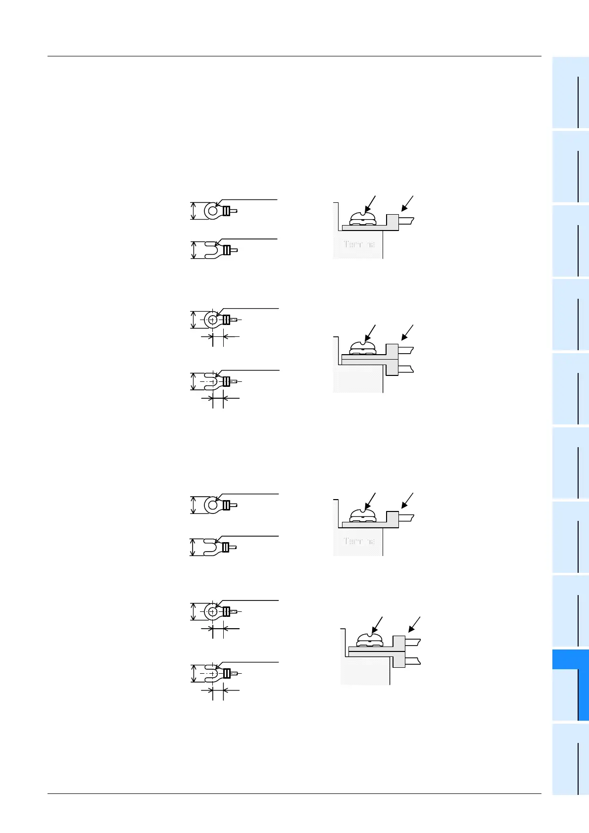
3. Wire end treatment
The solderless terminal size depends on the terminal screw size and wiring method.
- Use solderless terminals of the following size.
- Tighten the terminals to a torque of 0.5 N
•m to 0.8 N•m.
In the case of M3 terminal screw
Main unit, input/output powered extension unit/block and special function unit/block
• When one wire is connected to one terminal
• When two wires are connected to one terminal
In the case of M3.5 terminal screw
FX Series terminal block, FX
2N-20PSU, FX2N-8AD
• When one wire is connected to one terminal
• When two wires are connected to one terminal
TerminalTerminal
Terminal
screw
Crimp
terminal
6.2mm(0.24")
or less
φ
3.2(0.13")
6.2mm(0.24")
or less
φ
3.2(0.13")
Terminal
screw
Crimp
terminal
Terminal
6.2mm(0.24")
or less
φ
3.2(0.13")
6.3mm(0.25")
or more
6.2mm(0.24")
or less
φ
3.2(0.13")
6.3mm(0.25")
or more
6.8mm(0.27")
or less
φ
3.7(0.15")
TerminalTerminal
Terminal
screw
Crimp
terminal
6.8mm(0.27")
or less
φ
3.7(0.15")
6.8mm(0.27")
or less
φ
3.7(0.15")
6.0mm(0.24")
or more
Terminal
screw
Crimp
terminal
Terminal
6.8mm(0.27")
or less
φ
3.7(0.15")
6.0mm(0.24")
or more

 Loading...


