360
FX3U Series Programmable Controllers
User’s Manual - Hardware Edition
19 FX3U-7DM (Display Module)
19.7 Monitor/Test Mode [Excluding User-Registered Devices]
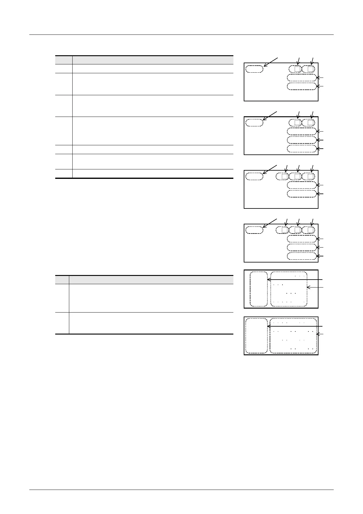
4. Counter [C]
5. Input [X] / Output [Y] / Auxiliary Relay [M] / State [S]
Display Content
[1]
Device No.
[2]
Contact image
ON:
OFF: Blank
[3]
Reset image
ON:
OFF: Blank
[4]
Count direction display
UP count:
DOWN count: Blank
(32-bit up/down counter and high-speed counter only)
[5]
Current value
[6]
Setting value or device specified by setting value (if an index
modifier is present, the index register’s device is also displayed).
[7]
Current value of device specified by setting value.
Display Content
[1]
Device No. at beginning of line.
Input (X) and output (Y): 8 points per line.
Auxiliary relay (M), special auxiliary relay (M), and state (S): 10
points per line.
[2]
ON/OFF status
ON: Last digit of device No..
OFF: " • ".
0
R
C0 P
0
01
0
R
C1 P
0
0001
D
C0 to C199
C0 to C199
[2] [3]
[6]
[7]
[1]
[5]
[5]
[6]
0
U
C0 R
1
-
C200 to C255
[3] [4]
[5]
[5]
[6]
02
P
[2]
0
U
C1 R
0
D
C200 to C255
[3] [4]
[5]
[5]
[6]
02
P
[2]
0001
[7]
D
[2]
[3]
[1]
[1]
[1]
X000 01234
X010 34567
X020 012 67
X030 56
[2]
[1]
M0
M10 3 67
M20
M30
[2]
2
45 89
45 8901
367012
[1]

 Loading...


