FX3U Series Programmable Controllers
User’s Manual - Hardware Edition
31
2 Features and Part Names
2.1 Major Features
1
Introduction
2
Features and
Part Names
3
Product
Introduction
4
Specifications
5
Version and
Peripheral
Devices
6
System
Configuration
7
Input/Output
Nos., Unit Nos.
8
Installation
9
Preparation and
Power Supply
Wiring
10
Input Wiring
[Input interruption function (with delay function)]
Interruption routines can be processed
preferentially by external signals with the minimum
ON or OFF width of 5
µ
s (X000 to X005).
(Timer interruption and high-speed counter
interruption functions are also provided.)
→ Refer to Chapter 10 "Input Wiring
Procedures (Input Interruption and Pulse
Catch)" in this manual and Programming
Manual.
[Pulse output function]
1) When output terminals in the transistor
output type main unit are used, pulses (open
collector outputs) of up to 100 kHz can be
output simultaneously to three axes (Y000,
Y001 and Y002).
2) When two high-speed output special adapters
FX
3U
-2HSY-ADP are used, pulses (differential
line driver outputs) of up to 200 kHz can be
output simultaneously to four axes.
→ Refer to Positioning Control Edition.
[Various positioning instructions]
→ Refer to Positioning Control Edition.
3. Display functions (display module)
FX
3U
-7DM Display Module (option) can be
incorporated in the PLC.
The display module can be mounted on the panel
by using the display module holder (option).
[Monitor/test function]
Devices can be monitored and tested by
operating the buttons on the display module.
The button operations can be inhibited by the
user program.
[Message display function]
User messages can be displayed on the display
module by the user program.
[Other functions]
On the display module, you can set the time,
adjust the contrast and display the PLC version
and error codes.
4. Communication and network functions
The expansion board, special adapter and
special function block for each communication
function can be connected.
[Kinds of communication functions]
• Programming communication through RS-
232C, RS-422 and USB
→ Refer to Data Communication Edition.
• Simple link between PCs
→ Refer to Data Communication Edition.
• Parallel link
→ Refer to Data Communication Edition.
• Computer link
→ Refer to Data Communication Edition.
• Inverter communication
→ Refer to Data Communication Edition.
• No-protocol communication through RS-232C/
RS-485
→ Refer to Data Communication Edition.
• CC-Link
- Master: FX
2N-16CCL-M
- Remote device station: FX
2N-32CCL
→ Refer to the manual for each product.
• CC-Link/LT
- Master: FX
2N-64CL-M
- Remote I/O station, Remote device station
→ Refer to the manual for each product.
• MELSEC I/O LINK
- Master: FX
2N-16LNK-M
- Remote I/O station
→ Refer to the manual for each product.
• AS-i system
- Master: FX
2N-32ASI-M
-Slave station
→ Refer to the manual for each product.
5. Analog functions
The special adapter and special function block
for each analog function are connected.
→ For information not given in Analog
Control Edition, Refer to the manual for each
product.
[Kinds of analog functions]
• Voltage/current input
• Voltage/current output
• Temperature sensor input (thermocouple and
platinum resistance thermometer sensor)
• Temperature control
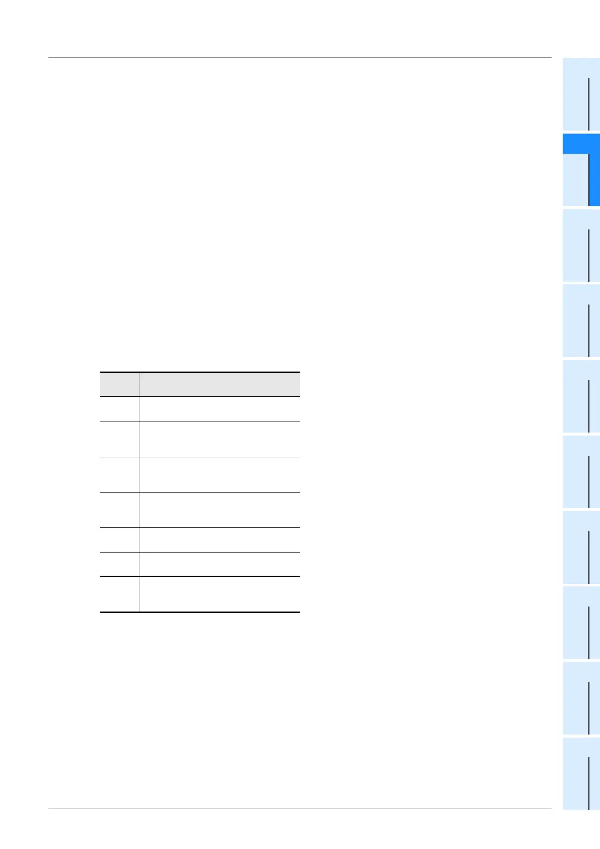
Instruc-
tion
Description
DSZR
Mechanical zero return instruction with
DOG search function
ABS
Instruction to read the current value
from our servo amplifier with absolute
position (ABS) detecting function
DRVI
Positioning (relative positioning) to
specify the movement from the current
position
DRVA
Positioning (absolute positioning) to
specify the target position based on the
current value 0
PLSV
Instruction to change the pulse train
output frequency
DVIT
Positioning for fixed-feed interruption
drive
TBL
Instruction for positioning based on
batch setting of positioning operation,
moving distance and speed

 Loading...


