FX3U Series Programmable Controllers
User’s Manual - Hardware Edition
33
2 Features and Part Names
2.2 Names and Functions of Parts
1
Introduction
2
Features and
Part Names
3
Product
Introduction
4
Specifications
5
Version and
Peripheral
Devices
6
System
Configuration
7
Input/Output
Nos., Unit Nos.
8
Installation
9
Preparation and
Power Supply
Wiring
10
Input Wiring
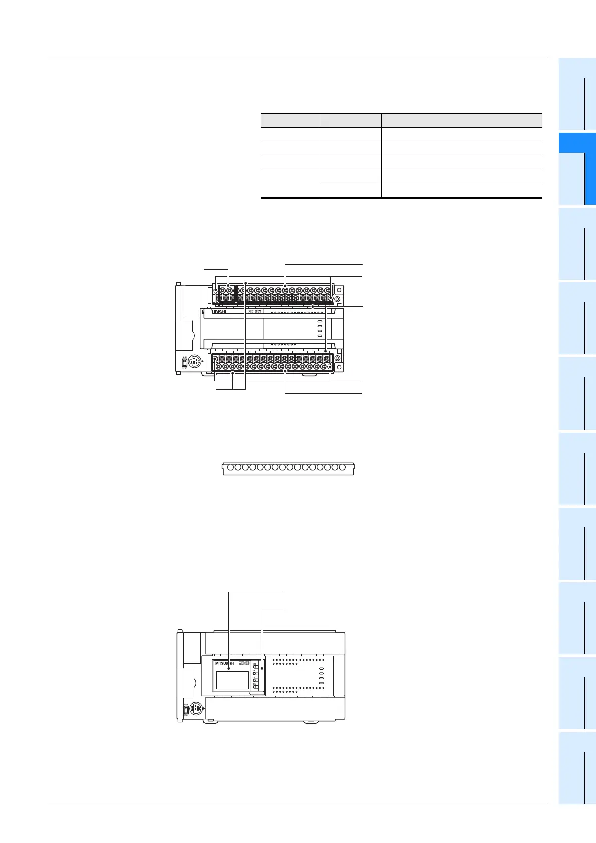
When the terminal block covers are open
When the display module (FX
3U-7DM) is installed
[12]
Operation status display LEDs The operation status of the PLC can be checked with the LEDs.
The LEDs turn off, light and flash according to the following table.
→ For details on the operation status, refer to Section 14.5.
[13]
Output display LEDs (red) When an output terminal (Y000 or more) is turned on, the corresponding
LED lights.
[14]
Power supply terminal Connect the power supply to the main unit.
[15]
Protective terminal
covers
A protective terminal cover (refer to the following drawing) is fitted to the lower
stage of each terminal block. (FX
3U-{{M/ES(S), and DS(S) are equipped.)
The cover prevents fingers from touching terminals, thereby improving safety.
[16]
Input (X) terminals Wire switches and sensors to the terminals.
[17]
Terminal block
mounting screws
If the main unit must be replaced, loosen the screws (slightly loosen the left and
right screws), and the upper part of the terminal block can be removed. (On FX
3U-
16M, the terminal block cannot be removed.)
[18]
Terminal names The signal names for power supply, input and output terminals are shown.
[19]
Output (Y) terminals Wire loads (contactors, solenoid valves, etc.) to be driven to the terminals.
[20]
Display module (FX3U-7DM)
The display module (option) can be installed.
[21]
Top cover (accessory to FX3U-
7DM)
A square hole is made so that the display module can be seen. Replace
the original top cover with this cover.
LED name Display color Description
POWER Green On while power is on the PLC.
RUN Green On while the PLC is running.
BATT.V Red Lights when the battery voltage drops.
ERROR
Red Flashing when a program error occurs.
Red Lights when a CPU error occurs.
FX
3U
-48MR/ES
FX
3U
-48MFX
3U
ERROR
RUN
BATT
POWER
R
0312
IN
OUT
645
21
7
20 2422 23 2625
10 11 1312 1614 15 17
27
0312 645
21
7
20 2422 23 2625
10 11 1312 1614 15 17
27
Y12Y10 Y16Y14 Y22Y20 Y26 COM5
COM1
Y24Y6
Y4Y2Y0
Y7 Y11 Y13Y5
COM2
Y3
Y1
COM3 Y15 Y17COM4 Y23 Y25 Y27Y21
X5
X0
X1
X2
X3 X7
X11
X13
X40VS/S
N 24V
X6 X10 X12 X14 X16 X20
L X27X23 X25X15 X17 X21
X24 X26X22
FX
3U
-48MR/ES
FX
3U
-48MFX
3U
ERROR
RUN
BATT
POWER
R
0312
IN
OUT
645
21
7
20 2422 23 2625
10 11 1312 1614 15 17
27
0312 645
21
7
20 2422 23 2625 27
Y12Y10 Y16Y14 Y22Y20 Y26 COM5
COM1
Y24Y6
Y4Y2Y0
Y7 Y11 Y13Y5
COM2
Y3
Y1
COM3 Y15 Y17COM4 Y23 Y25 Y27Y21
X5
X0
X1
X2
X3 X7
X11
X13
X40VS/S
N 24V
X6 X10 X12 X14 X16 X20
L
X27X23 X25X15 X17 X21
X24 X26X22
[14] Power supply terminal
[16] Input (X) terminals
[19] Output (Y) terminals
[17] Terminal block mounting screws
[18] Terminal names
[17] Terminal block mounting screws
[15] Protective terminal covers
FX3U-48MR/ES
FX
3U
-48MFX
3U
ERROR
RUN
BATT
POWER
R
0312
IN
OUT
645
21
7
20 2422 23 2625
10 11 1312 1614 15 17
27
0312 645
21
7
20 2422 23 2625
10 11 1312 1614 15 17
27
Y12Y10 Y16Y14 Y22Y20 Y26 COM5
COM1
Y24Y6
Y4Y2Y0
Y7 Y11 Y13Y5
COM2
Y3
Y1
COM3 Y15 Y17COM4 Y23 Y25 Y27Y21
X5
X0
X1
X2
X3 X7
X11
X13
X40VS/S
N 24V
X6 X10 X12 X14 X16 X20
L X27X23 X25X15 X17 X21
X24 X26X22
FX
3U
ERROR
RUN
BATT
POWER
R
0312
IN
OUT
645
21
7
20 2422 23 2625
10 11 1312 1614 15 17
27
0312 645
21
7
20 2422 23 2625
10 11 1312 1614 15 17
27
Y12Y10 Y16Y14 Y22Y20 Y26 COM5
COM1
Y24Y6
Y4Y2Y0
Y7 Y11 Y13Y5
COM2
Y3
Y1
COM3 Y15 Y17COM4 Y23 Y25 Y27Y21
X5
X0
X1
X2
X3 X7
X11
X13
X40VS/S
N 24V
X6 X10 X12 X14 X16 X20
L
X27X23 X25X15 X17 X21
X24 X26X22
[20] Display module (FX3U-7DM)
[21] Top cover (accessory to FX
3U-7DM)

 Loading...


