19.6 Backlight Replacement
19.6.2 Replacement procedure of backlight
19 - 14
17
ADDITION TIMES RESET
FOR MAINTENANCE TIME
NOTIFICATION
18
INSTALLATION OF
COREOS, BOOTOS AND
STANDARD MONITOR OS
19
MAINTENANCE AND
INSPECTION
20
TROUBLESHOOTING
APPENDICESINDEX
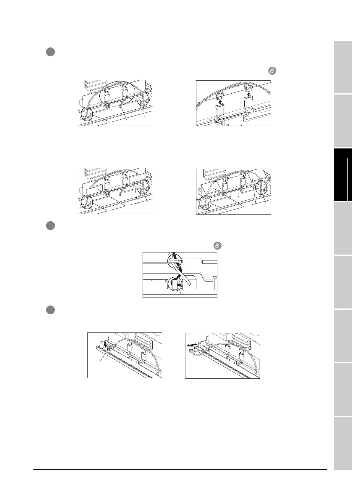
6 Disconnect the cable connector of the upper (H01) backlight and the cable connector of the lower (H02)
backlight from the GOT side connectors.
When the GOTs with the following hardware versions are used, remove the cables from the insulation
sheets for protecting cables.
7 Remove the cables of the upper connector (H01) from the 2 slits (black).
Similarly, remove the cables of the upper connector (H02) from the 2 slits (black).
(Expanded figure of part B in )
8 Press the upper backlight fixing latch (black) with your finger, and pull out the backlight to the left.
Similarly, press the lower backlight fixing latch (black) with your finger, and pull out the backlight to the
left.
(Expanded figure of part A in )
• GT1565-VTBA(Hardwear version W to AY)
• GT1565-VTBD(Hardwear version N to AL)
• GT1565-VTBA(Hardwear version AZ or later)
• GT1565-VTBD(Hardwear version AM or later)
B
A
B
B
B
Insulation sheets
for protecting cables
B
B
Insulation sheets
for protecting cables

 Loading...

