Appendix 1 External Dimensions
App - 11
17
ADDITION TIMES RESET
FOR MAINTENANCE TIME
NOTIFICATION
18
INSTALLATION OF
COREOS, BOOTOS AND
STANDARD MONITOR OS
19
MAINTENANCE AND
INSPECTION
20
TROUBLESHOOTING
APPENDICESINDEX
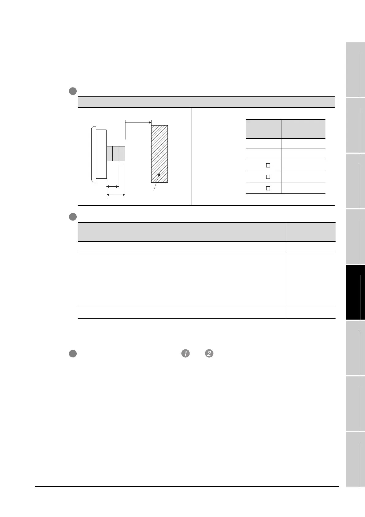
(7) Depth dimensions for installing multiple stages
The following shows how to calculate the depth dimensions for installing multiple stages to the
GOT.
When installing only the first stage , refer to the dimensions in App.1 (6).
1 Select the GOT main unit coefficient from the following list.
2 Select the option coefficient of the corresponding extension unit from the following list.
Unit: mm (inch)
*1 When installing GT15V-75V4, GT15V-75R1, GT15V-75V4R1, GT15V-75ROUT and GT15-J71GP23-SX, GT15-
J71GF13-T2, install GT15-J71GP23-SX, GT15-J71GF13-T2 in the second stage.
3 Substitute the coefficients selected in and to the following formula.
4 E (for 2 stages) = G (GOT main unit coefficient) + H (option coefficient) + H (option coefficient)
5 F (for 3 stages) = G (GOT main unit coefficient) + H (option coefficient) + H (option coefficient) +
H (option coefficient)
GOT side face
Model name
H (option
coefficient)
GT15-CFCD, GT15-CFEX-C08SET 20.5(0.81)
GT15V-75V4
*1
, GT15V-75R1
*1
, GT15V-75V4R1
*1
, GT15V-75ROUT
*1
,
GT15-QBUS, GT15-QBUS2, GT15-ABUS, GT15-ABUS2,
GT15-RS2-9P, GT15-RS4-9S, GT15-RS4-TE, GT15-J71E71-100,
GT15-J71LP23-25, GT15-J71BR13, GT15-J71LP23-Z, GT15-J71BR13-Z,
GT15-J61BT13, GT15-J61BT13-Z, GT15-PRN, GT15-DIO, GT15-DIOR,
GT15-SOUT
21.5(0.85)
GT15-J71GP23-SX
*1
, GT15-J71GF13-T2
*1
35.5(1.4)
Example) A calculation example is shown below.
F dimension (for 3 stages) for installing a video input unit (GT15-75V4) in the first
stage, a CC-Link IE Controller Network communication unit (GT15-J71GP23-SX) in
the second stage and a CF card unit (GT15-CFCD) in the third stage of the GT1595
F (for 3 stages) = -0.5 (main unit coefficient of GT1595) + 21.5(option coefficient of
GT15-75V4) + 35.5 (GT15-J71GP23-SX) + 20.5 (GT15-CFCD)
= 77
The dimension after installing the above-mentioned extension units is F=77mm.
Other equipment
100(3.94) or more
E
F
Unit: mm (inch)
GOT type
G (main unit
coefficient)
GT1595 -0.5(-0.02)
GT1585 -3.5(-0.14)
GT157
-0.5(-0.02)
GT156
1.5(0.59)
GT155
1.5(0.59)

 Loading...

