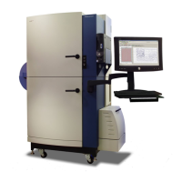
FLIPR
®
Tetra High Throughput Cellular Screening System User Guide
0112-0109 H 151
3. Select the appropriate Plate Format from the 96, 384, or 1536
options and select the LED/Filter pair you want to calibrate
from the drop-down list.
4. Place the Flat Field Calibration Plate into the Read Position.
The Flat Field Calibration Plate may be a Molecular Devices
supplied plate or a Read Plate loaded with an appropriate dye
for the LED/Filter wavelength pair being calibrated.
Molecular Devices supplied yellow, 96-, 384- or 1536-well plate
can be used to Flat Field calibrate the following LED/Filter
pairs.
390–420 nm/565–625 nm
420–455 nm/475–505 nm
420–455 nm/515–575 nm
470–495 nm/515–575 nm
470–495 nm/565–625 nm
495–505 nm/526–586 nm
510–545 nm/565–625 nm
610–626 nm/646–706 nm
The following dye should be used to calibrate the respective
LED/Filter pair.
360–380 nm/400–460 nm with MQAE (detailed instructions
for handling MQAE are outlined in the MQAE section).
390–420 nm/440–480 nm with Coumarin (detailed
instructions for handling Coumarin are outlined in the
Coumarin section).
5. Once the appropriate plate is placed in the Read Plate position,
select the Flat Field Calibration button. The calibration is
complete when the Assay Finished (Unlock) light is
illuminated on the instrument and the LED/Filter pair is
identified as Done under the Flat Field cal column.
6. When complete, select Close to exit the Calibration dialog.
7. Place your yellow signal test plate of the appropriate well format
into your system.
8. Perform a signal test by selecting Yellow Plate Signal Test
from the Instrument/Manual Operation menu, or using the
corresponding button. The yellow plate standard deviation
should be 5% or less.
Note: None indicates either no LEDs are illuminated or the
instrument used a blank emission filter position to create the
calibration file.

 Loading...