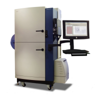
System Hardware Features
36 0112-0109 H
Typically, the two LED bank pairs are set up with LEDs of different
wavelengths, for example., one pair might have LEDs of range 470 nm
to 495 nm, while the other pair might be 510 nm to 545 nm.
Ratiometric experiments can be set up to use both of these
wavelengths, in which case the paired banks fire alternately.
Deflectors around the LED banks direct all light from the LEDs through
excitation bandpass filters that further refine the wavelength. The light
is then funneled into light pipes that focus it onto the base of the read
plate.
The FLIPR
®
Tetra System will not operate without the full complement
of LED banks installed, however blank LED banks can be used for one
pair if only one excitation wavelength is available. Unless additional LED
banks are ordered with a purchase, FLIPR
®
Tetra Systems are shipped
with a set of default calcium LED banks (470–495 nm) and a set of
blank LED banks.
Configuration of LEDs for an experiment is mostly carried out in
ScreenWorks Software in the Settings window; see Setup Read Mode
on page 72 for details. LED banks can be changed by the user in
approximately 10 minutes; refer to Exchanging LED Modules on
page 138 for instructions.
LEDs do not need time to warm up prior to running an experiment.
Startup time is only dependent on the time it takes for the camera to
cool down and for the stage to heat up, if this option is used.
The LEDs are air-cooled by fans, however the light output varies
slightly as they heat up. To help with the heat transfer, a piece of foam
in inserted in the back of the LED bank on each side. Also to counteract
the temperature change, a temporal correction is automatically applied
to the LED feedback circuit to normalize the system.
Flat field calibration is automatically applied to the read plate to adjust
for non-uniformity of illumination across the plate. Refer to Optical
Calibration on page 149 for instructions on how to manually calibrate
the system.
Note: Despite the two excitation wavelengths firing alternately,
output data files show time points for each as occurring
simultaneously.
WARNING! Do not look into LED banks when turned on,
especially at intensities over 30% or in the UV spectrum,
unless you are viewing them through the observation panel. If
light is seen escaping the instrument when the LED modules
are turned on, shut down immediately and call Molecular
Devices Technical Support.

 Loading...