M Series AC Servo
User Manual
136
Rev. 1.0
7/31/2019
400-820-9661
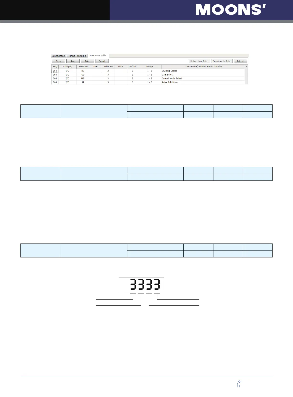
In M servo suite parameter table section, it is divided into 4 parameters, GS represents bit 1, DS
represents bit 2, MS represents bit 3. PI represents bit 4
Please also refer to 7.1.4 gain selection function, 7.1.5 control mode selection, 7.2.3 input electronic
gearing selection, and 7.2.4 pulse inhibition function
P-66 (AO) Alarm output function setting
Data Range Default Unit Data type
1~3 3 --- DEC
Denes usage of digital output Y1. Normally this output is used to indicate an Alarm caused by a Drive
Fault. This output can being recongured as a general purpose output for use with other types of output
commands. There are three states that can be dened: AO1: Output Y1 is closed (active, low) when
a Drive Fault is present. AO2: Output Y1 is open (inactive, high) when an Drive Fault is present. AO3:
Output Y1 is not used as an Alarm Output and can be used as a general purpose output.
P-67 (BO) Motor brake control setting
Data Range Default Unit Data type
1~3 3 --- DEC
BO defines usage of digital output Y2 as the Brake Output, which can be used to automatically activate
and deactivate a holding brake. Output Y2 can also be configured as a general purpose output for use
with other types of output commands. There are three states that can be defined:
BO1: Output Y2 is closed (energized) when drive is enabled, and open when the drive is disabled.
BO2: Output Y2 is open (de-energized) when drive is enabled, and closed when the drive is disabled.
BO3: Output Y2 is not used as a Brake Output and can be used as a general purpose output.
Please also refer to 7.1.7 motor brake control
P-68 (MO)
Y3,Y4,Y5,Y6 output function
setting
Data Range Default Unit Data type
3333 --- HEX
P-68 (MO) denes Y3,Y4,Y5,Y6 output functions. It is based on digits from right to left.
Bit4 Output6 Function Bit1 Output3 Function
Bit2 Output4 Function
Bit3 Output5 Function
Defines the drive
’
s Motion Output digital output function on output Y3. There are three Motion Output
states that can be defined:
8: When the output torque reached the targeted torque, output Y3 is closed
9: When the output torque reached the targeted torque, output Y3 is open
3: Output Y3 is used as general output.
Defines the drive
’
s Motion Output digital output function on output Y4. There are five Motion Output
states that can be defined: