SP Pump Diagnostics and Repair
B-11
Part 1128350_02
E 2020 Nordson Corporation
1
2
a
b
a
b
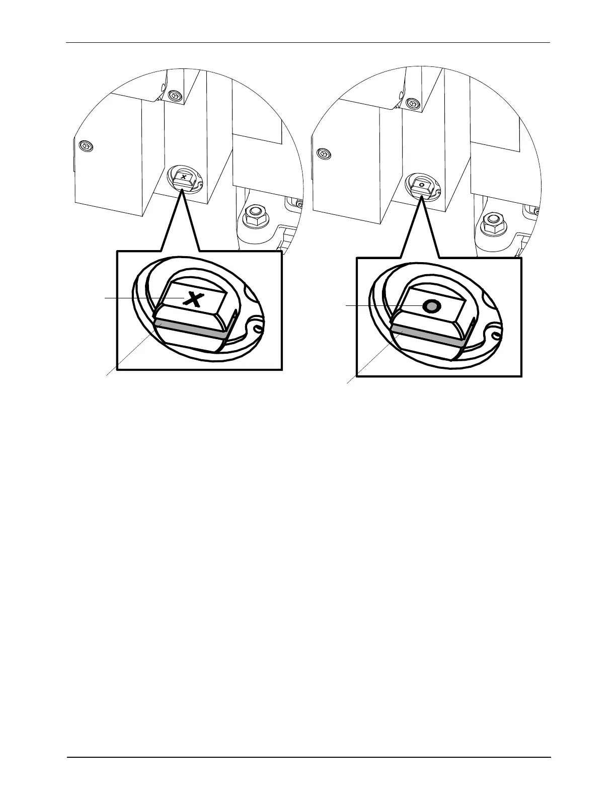
Figure B-2 Isolation valve close/open slots locations
1. Isolation valve is closed; the “X” mark is visible on the
valve
a: Isolation valve slot/b: X mark (closed)
2. Isolation valve is open; the “O” mark is visible on the
valve
a: Isolation valve slot/b: O mark (open)
To make sure that the isolation valve isclosed,theslotmustbepositioned
horizontal with the “X” mark visible. See item 1 in Figure B-2.
To make sure that t he isolation valve is open, the slot must be positioned
horizontal with the “O” mark visible. See item 2 in Figure B-2.
6. Disconnect the air line from the back of the pump.
7. Loosen, but do not remove, the two M6 screws at the base of the pump.
8. Grasp the pump and rotate it clockwise to disengage it from t he two M6
screws.