Installation
3-4
Part 1128350_02
E 2020 Nordson Corporation
Installation Requirements
Before installing the melter, ensure that the desired installation location
provides the required clearances, environmental conditions, and utilities.
Melter Clearances
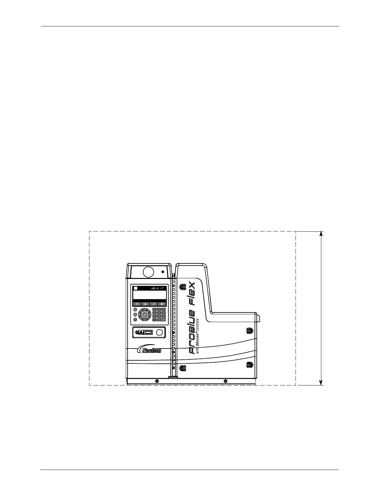
Figures 3-1 and 3-2 show the recommended clearances around the melter.
Using the figures will ensure setting of the minimum clearances that are
required between the melter and:
- Hoses
- Cordsets
- Power cabling
- Tank lid
- E-Box door
- Air supply
- Pump
NOTE: For melter dimensions and drawings, refer to Technical Data
(Section 7).
635 mm (25.0 in.)
Figure 3-1 Installation clearances around the melter