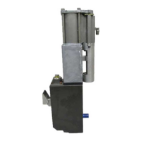
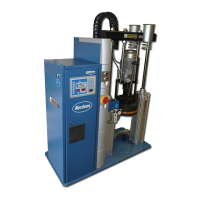
ProBlue Flex 400/480 Volt Transformer
F-18
Part 1128350_02
E 2020 Nordson Corporation
Mounting the 400/480V Melter on the Transformer (contd)
WARNING! Risk of personal injury or equipment damage. Installation of the
melter requires two people.
3. Route cables bet ween the transformer and the ProBlue Flex melter
throughthetwosidespacersasshowninFigureF-13.
4. Slide the melter forward so that the melter locking tabs securely connect
with the transformer.
5. Secure the melter to the transformer using the two M8x1.25X20 screws
that are provided in the installation kit.
6. Coil the three transformer wire harnesses and temporarily stow them in
the terminal block area.
Connecting Transformer to the Melter
Refer to the Wiring Diagrams given later in the manual for individual electrical
board drawings.
1. Route one wire harness from the transformer up into the melter's E-Box
enclosure as shown in Figure F-13.
SeeFigureF-14.
2. Connect the transformer's power harness into terminals X9 and X10 on
theE-Box'spowerdistributionboard.
3. Connect two control harnesses from the transformer into terminal X6 and
X12 on the E-Box's 6-Channel power board.
4. Connect the heater power harness from the transformer to the heater
power harne ss plug that enters the bottom of the melter's electrical
enclosure.
5. Connect the ground lead (external protective grounding conductor) to the
ground tree that is located on the melter chassis.

 Loading...


