NTI ENTERPRISE ENVIRONMENT MONITORING SYSTEM
96
Advanced-Cascade Configuration
From the Administration->Advanced>Cascade menu, the administrator can configure the ENVIROMUX to either be
a master system,
an Ethernet slave
an RS485 local slave
In a cascaded configuration, there can be 1 master unit and up to 4 slave units.
A cascaded configuration can consist of one or more Ethernet slaves and one or more RS485 slaves, but a maximum of 4 slaves
total.
Notes:
-When ENVIROMUX units are connected as slaves, only their sensors and output relays are used and are
monitored through the master unit.
-Only E-16D units can be used as Master and Slaves in an RS485 cascaded configuration.
-E-16D,-5D and -2D units can be Master or Slaves when cascading via Ethernet.
-E-2D used in a cascaded configuration must be the “REV C” design (includes 2- 9VDC power jacks).
-After setting up cascading for ENVIROMUX units, we recommend re-booting the slaves completely before re-booting
the master to have the master properly recognize the slaves and their sensors.
-Do not configure sensors from the Slave web interface, do not put a check in “Ad to datalog” (page 42) and do not
enable any alert methods. Only enable datalogging and alert methods for sensors when configuring them from the
Master interface. Otherwise accumulative data at the Slave will cause a loss in communication with the Master.
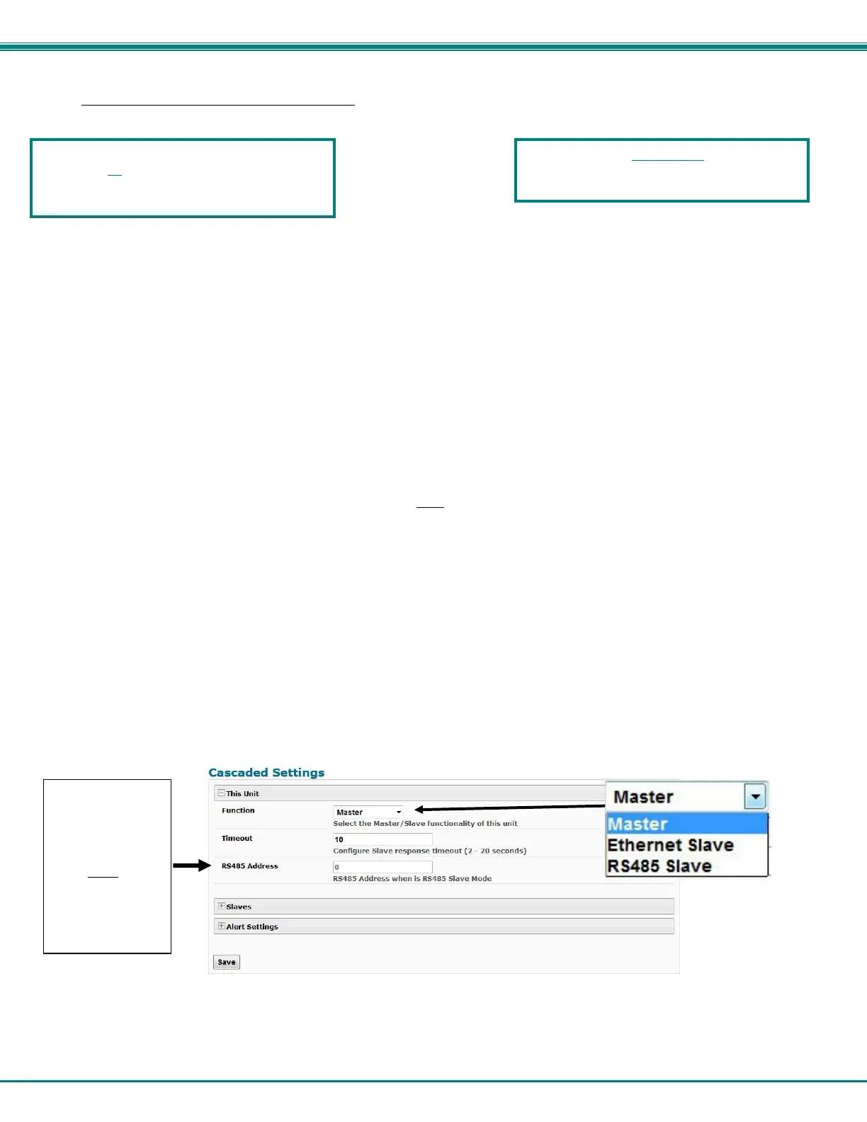
1. Go to the Administration -> Cascading page for each ENVIROMUX and using the choices in the drop down box
(Figure 106), select the position each ENVIROMUX will h
old in the cascaded system.
If you select Ethernet Slave, make sure each Ethernet Slave has a unique IP address (must be different from the
Master unit and any other Ethernet Slave). With “Ethernet Slave” selected and a unique IP address assigned,
press “Save” and exit the web interface. This unit will be controlled and configured from the Master unit web
interface.
If you select RS485 Slave (E-16D only), also enter an RS485 address value from 1-255 to be used when defining
what RS485 slaves are part of a cascaded configuration. Make note of the address entered. Each RS485 slave
must have a unique address, but any value from 1-255 can be used. Once the address values have been saved,
connect the RS485 slaves to the master as described in step 2 (Figure 107).
If you select Maste
r, then be sure to designate and connect the Slave units properly (unique IP addresses must be
assigned for Ethernet Slaves and unique RS485 addresses assigned to RS485 Slaves and connected as shown in
Figure 107 and Figure 108) before continuing to step 4. To
prevent unnecessary alert messages due to LAN
connectivity issues, configure a response timeout value between 2 and 20 seconds. This will be the amount of time
that a slave must have lost connection before an alert message regarding connectivity will be sent. This will apply
to all connected slaves.
Figure 106- Cascade configuration options
When cascading via Ethernet, the E-16D, -
5D or -2D can be used as master or slave in
any combination.
Enter a unique
value between 1-
255 if “RS485
Slave” is selected.
(Each RS485
slave must
have a
different RS485
address. )
Otherwise, leave
this blank.
If one E-xD in a cascaded system is at firmware
version 3.0, all
units must be at firmware version
3.0 or later. To update firmware, see page 95.
Update slaves first, then the master.

 Loading...