NTI ENTERPRISE ENVIRONMENT MONITORING SYSTEM
130
WIRING METHODS
RS485 Sensor Cable
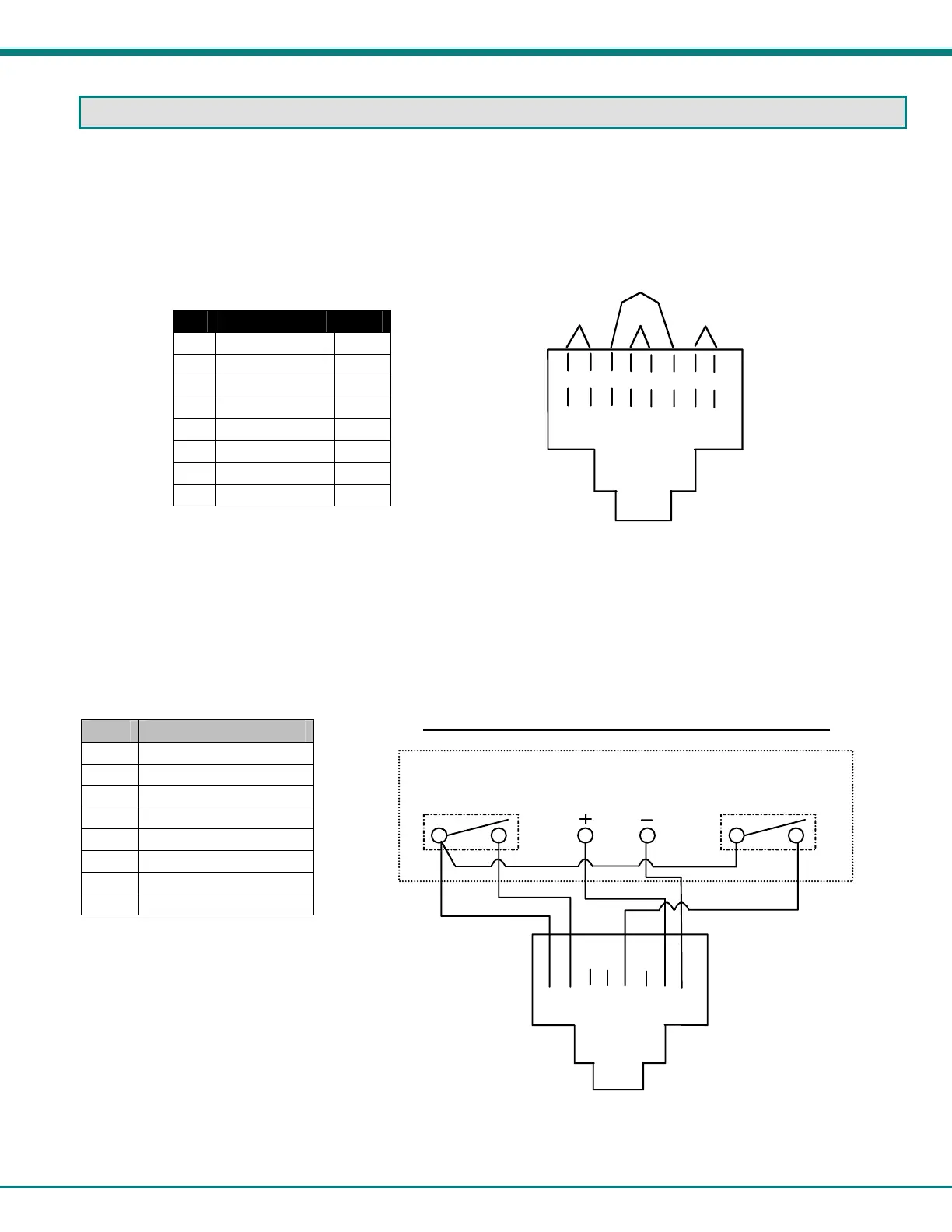
The CAT5 connection cable between the ENVIROMUX and the external RS485 Sensors (page 10) is terminated with RJ45
connectors and must be wired according to the EIA/TIA 568 B industry standard. Wiring is as per the table and drawing below.
Pin Wire Color Pair
1 White/Orange 2
2 Orange 2
3 White/Green 3
4 Blue 1
5 White/Blue 1
6 Green 3
7 White/Brown 4
8 Brown 4
Contact Sensor Wiring
When applying CAT5 cables to contact sensors for plug-in to the RJ45 Sensor sockets, the following socket-to-sensor wiring must
be followed:
RJ45 Sensor Socket Pinout
Pin # Pin Name
1 GND
2 SENSE
3 RS485 +
4 +5 VDC
5 TAMPER SWITCH
6 RS485 -
7 +12 VDC
8 GND
T
1
+
R
2
-
T
3
+
R
4
-
T
5
+
R
6
-
T
7
+
R
8
-
Pair 2 Pair 1
Pair 4
Pair 3
(View Looking into RJ45 Socket)
12
3
4
56
78
12VDC
ALARM
TAMPER
Pins 3,4, and 6
are not used
for contact
sensors
View looking into RJ45 Socket
Contact Sensor
wht/orange
orange
wht/blue
brown
wht/brown
Schematic for wiring Contact Sensor to RJ45 Socket
jumper
For 5VDC contact
sensors, substitute
pin 4(5VDC) for
pin 7 (12VDC).
 Loading...