NTI ENTERPRISE ENVIRONMENT MONITORING SYSTEM
44
Alert Settings (Applies to Critical and Non-Critical Alerts except where noted) (Cont’d)
Associated Output Relay
Tip: Another way to have a
single output relay react to
the changes of more than
one sensor is to use Events
and Smart Alerts (page 102)
to create that association.
You can associate the sensor with the operation of the output relay, or not.
By Default, the operation of an output relay can only be associated with one sensor or IP
Device.
To associate an output relay with more than one sensor or IP Device, place a checkmark in the
checkbox under “System- Other Options- Disable Relay Interlock (page 70).
Note: If the Output Relay is associated with a sensor/device, and configured to change
state when a sensor crosses threshold into alert, it will change state even if the alerts are
disabled.
Note: Only one sensor/device should be associated with the Output Relay at a time.
Contradicting commands from two or more sensors will result in the output relay
responding to the state directed by the last command received.
Output Relay Status on Alert State the output relay will be in when sensor goes to an alert
Output Relay Status on Return
from Alert
State the output relay will be in when sensor is no longer in alert
Data Logging
Add to data log This is a check-box that lets the user decide if the data sampled should be recorded in the Data
Log.
Logging Period Enter the time period between logged measurements
Be sure to press the Save button to save the configuration settings.
Groups
Groups are used to create a common relationship between sensors, IP devices, etc. and their alert messages. Each item being
monitored can be assigned to one or more groups (up to 8 possible). Users (a maximum number of 17 including the root user)
can receive alert messages from items in one or more groups (see user configuration on page 82).
Test Alerts
With all configuration settings completed, each sensor and how the ENVIROMUX will react to an alert condition can be tested.
Press the Simulate Alert button at the bottom of the configuration page to test each of the notification methods configured. To
cancel the simulation, press the Clear button.
Note: A simulated alert will test all settings including any delay that has been configured (i.e. if a 2 minute delay is
configured, it will delay sending the email for 2 minutes)
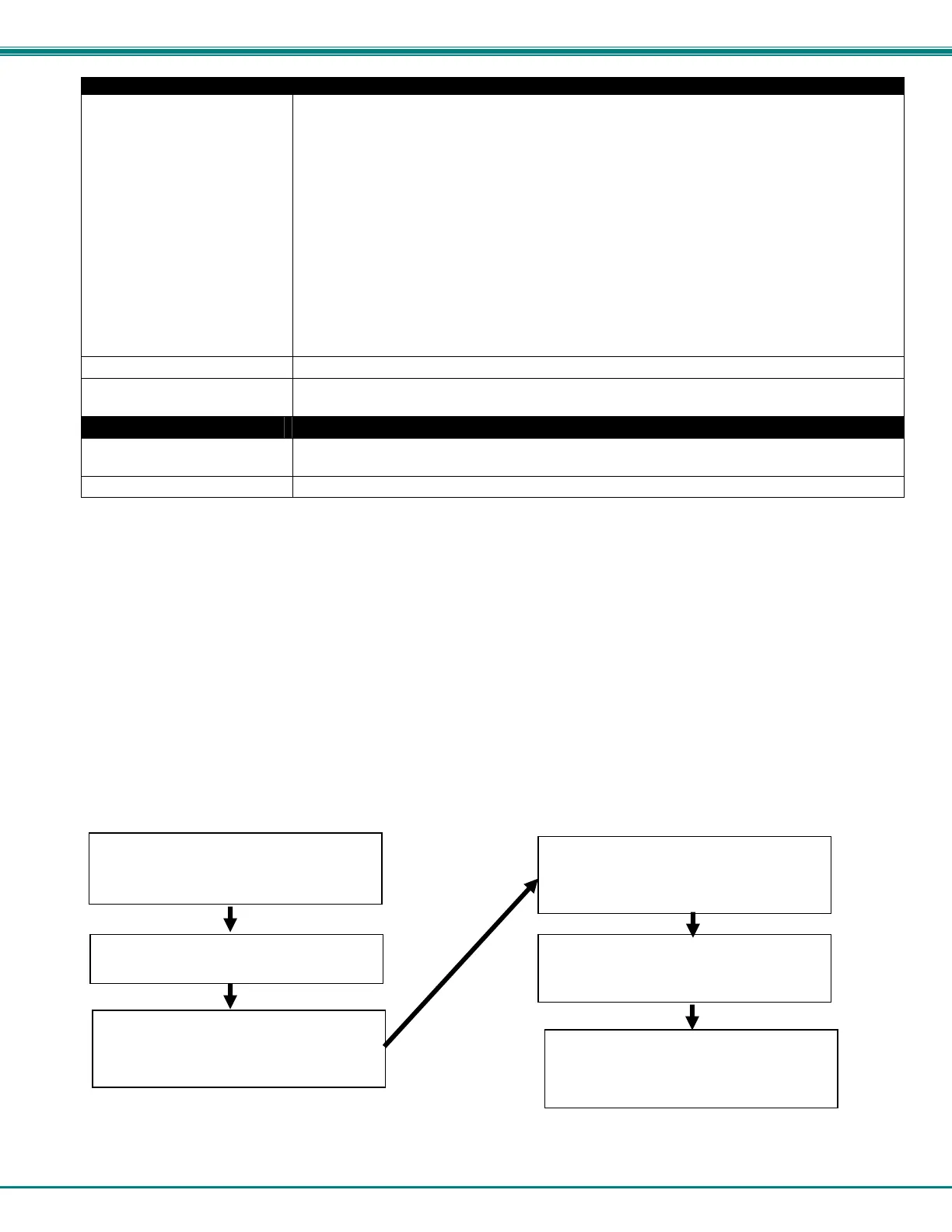
To perform a test, the ENVIROMUX must be properly setup for a user to receive alert messages. Use the chart below to make
sure the ENVIROMUX is setup properly.
Figure 41- Chart to setup alert notification
Fill in Network Page with valid information
(see page 67)
Create a user profile- be sure to include
valid user e-mail address and assign at
least one group to user to receive
messa
es from (pa
e 74)
Configure sensor and assign sensor to a
group. For a user to receive messages
from this sensor, this group must be
selected in the user profile (above).
se the “Simulate Alert” button to test the
sensor configuration. The sensor will send
a message to the assigned group.
he user will receive the message from the
group as configured in the alert notification
methods on the sensor configuration page
(page 41).
Apply a valid e-mail address for the
ENVIROMUX to the Enterprise Setup Page
(see page 64)
 Loading...