3.5.7 Interface to DMA Controller
When all three debug messages A, B, C have been received in the correct order, M_CAN
DMA request signal is activated to trigger a DMA transfer. The RAM words holding
debug messages A, B, C will not be changed by the M_CAN while M_CAN DMA
request signal is active.
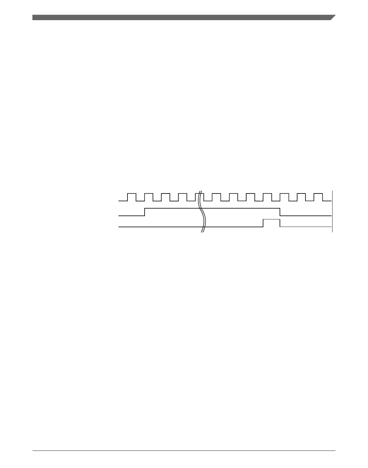
After the transfer of the received messages has completed the DMA unit activates the
M_CAN DMA acknowledge signal. This resets M_CAN DMA request signal. The debug
message handling state machine enters idle state (DMS = 00) and waits for reception of
the next debug messages.
NOTE
If the DMA unit activates the M_CAN DMA acknowledge
signal before the DMA transfer has completed, the Rx Buffer
elements holding debug messages A, B, C are unlocked and
may be overwritten by received debug messages.
M_CAN DMA request
M_CAN DMA acknowledge
M_CAN host clk
Figure 3-60. Timing of DMA Interface Signals
Chapter 3 Modular CAN (M_CAN)
MPC5777C Reference Manual Addendum, Rev. 1, 12/2015
Freescale Semiconductor, Inc. 115

 Loading...


