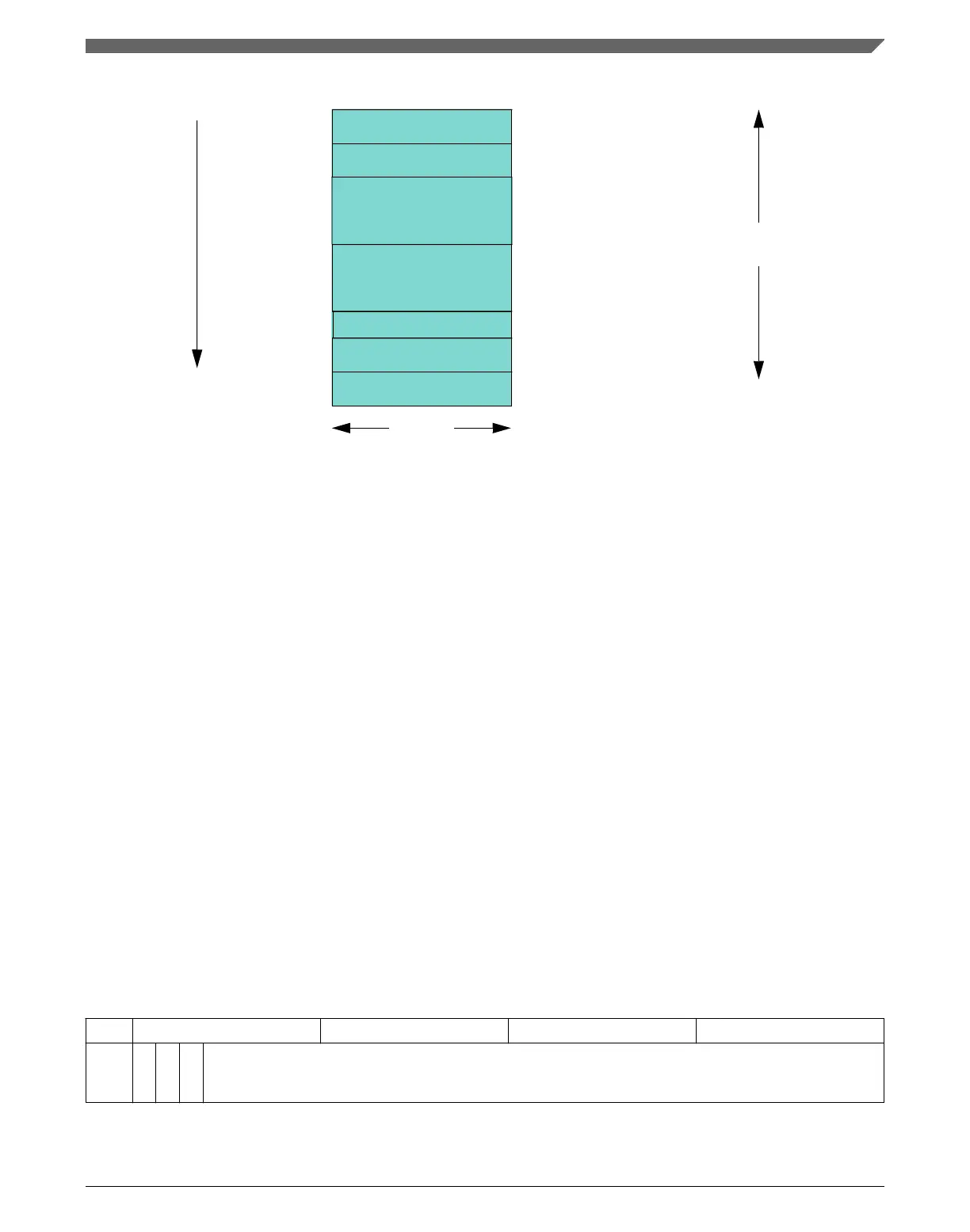
Rx FIFO 0
Rx FIFO 1
Tx Buffers
Tx Event FIFO
11-bit Filter
29-bit Filter
max. 4352 words
0-64 elements / 0-1152 words
0-64 elements / 0-1152 words
0-32 elements / 0-576 words
0-32 elements / 0-64 words
0-128 elements / 0-128 words
0-64 elements / 0-128 words
32 bits
RXF0C[F0SA]
RXF1C[F1SA]
TXBC[TBSA]
TXEFC[EFSA]
SIDFC[FLSSA]
XIDFC[FLESA]
Start Address
Rx Buffers
RXBC[RBSA]
0-64 elements / 0-1152 words
Figure 3-48. Message RAM configuration
When the M_CAN addresses the Message RAM, it addresses 32-bit words, not single
bytes. The configurable start addresses are 32-bit word addresses: only bits 15 to 2 are
evaluated, and the two least significant bits are ignored.
NOTE
The M_CAN does not check for erroneous configuration of the
Message RAM. To avoid falsification or loss of data, carefully
configure in particular the start addresses of the different
sections and the number of elements of each section.
3.4.1 Rx Buffer and FIFO Element
Up to 64 Rx Buffers and two Rx FIFOs can be configured in the Message RAM. Each Rx
FIFO section can be configured to store up to 64 received messages. The structure of a
Rx Buffer / FIFO element is shown in the following table. The element size can be
configured for storage of CAN FD messages with up to 64 bytes data field via register
RXESC.
Table 3-48. Rx Buffer and FIFO Element
31 24 23 16 15 8 7 0
R0
E
SI
X
T
D
R
T
R
ID[28:0]
Table continues on the next page...
Chapter 3 Modular CAN (M_CAN)
MPC5777C Reference Manual Addendum, Rev. 1, 12/2015
Freescale Semiconductor, Inc. 79

 Loading...


