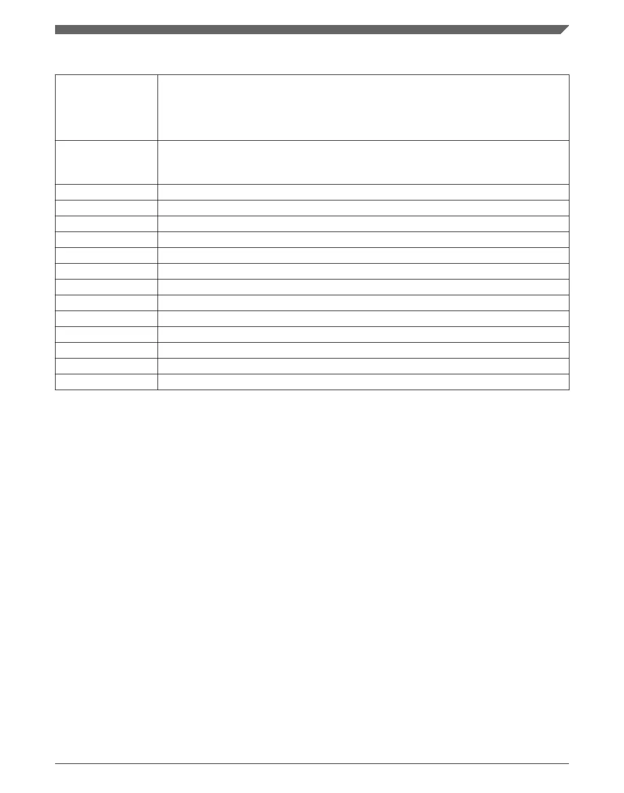
Table 3-49. Rx Buffer and FIFO Element Descriptions (continued)
R1 Bits 19:16 DLC[3:0]: Data Length Code
0-8 CAN + CAN FD: received frame has 0-8 data bytes
9-15 CAN: received frame has 8 data bytes
9-15 CAN FD: received frame has 12/16/20/24/32/48/64 data bytes
R1 Bits 15:0 RXTS[15:0]: Rx Timestamp
Timestamp Counter value captured on start of frame reception. Resolution depending on
configuration of the Timestamp Counter Prescaler TSCC[TCP].
R2 Bits 31:24 DB3[7:0]: Data Byte 3
R2 Bits 23:16 DB2[7:0]: Data Byte 2
R2 Bits 15:8 DB1[7:0]: Data Byte 1
R2 Bits 7:0 DB0[7:0]: Data Byte 0
R3 Bits 31:24 DB7[7:0]: Data Byte 7
R3 Bits 23:16 DB6[7:0]: Data Byte 6
R3 Bits 15:8 DB5[7:0]: Data Byte 5
R3 Bits 7:0 DB4[7:0]: Data Byte 4
... ...
Rn Bits 31:24 DBm[7:0]: Data Byte m
Rn Bits 23:16 DBm-1[7:0]: Data Byte m-1
Rn Bits 15:8 DBm-2[7:0]: Data Byte m-2
Rn Bits 7:0 DBm-3[7:0]: Data Byte m-3
NOTE
Depending on the configuration of the element size (RXESC),
between two and sixteen 32-bit words (Rn = 3 ..17) are used for
storage of a CAN message’s data field.
3.4.2 Tx Buffer Element
The Tx Buffers section can be configured to hold dedicated Tx Buffers as well as a Tx
FIFO / Tx Queue. In case that the Tx Buffers section is shared by dedicated Tx buffers
and a Tx FIFO / Tx Queue, the dedicated Tx Buffers start at the beginning of the Tx
Buffers section followed by the buffers assigned to the Tx FIFO or Tx Queue. The Tx
Handler distinguishes between dedicated Tx Buffers and Tx FIFO / Tx Queue by
evaluating the Tx Buffer configuration TXBC.TFQS and TXBC.NDTB. The element size
can be configured for storage of CAN FD messages with up to 64 bytes data field via
register TXESC.
Chapter 3 Modular CAN (M_CAN)
MPC5777C Reference Manual Addendum, Rev. 1, 12/2015
Freescale Semiconductor, Inc. 81

 Loading...


