2.1.3 Bus Bridge Configuration Register 2 (PCM_IAHB_BE2)
Address: 0h base + 8h offset = 8h
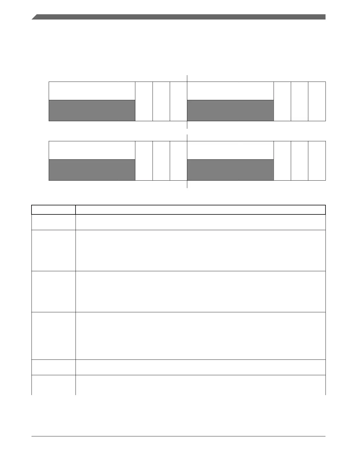
Bit 0 1 2 3 4 5 6 7 8 9 10 11 12 13 14 15
R
0
PRE_
FEC
BRE_
FEC
BWE_FEC
0
PRE_
M6
BRE_M6
BWE_M6
W
Reset
0 0 0 0 0 1 1 1 0 0 0 0 0 1 1 1
Bit
16 17 18 19 20 21 22 23 24 25 26 27 28 29 30 31
R
0
PRE_DMA_B
BRE_DMA_B
BWE_DMA_B
0
PRE_DMA_A
BRE_DMA_A
BWE_DMA_A
W
Reset
0 0 0 0 0 1 1 1 0 0 0 0 0 1 1 1
PCM_IAHB_BE2 field descriptions
Field Description
0–4
Reserved
This field is reserved.
This read-only field is reserved and always has the value 0.
5
PRE_FEC
Pending Read Enable FEC
This bit controls the bus gasket’s handling of pending read transactions.
0 Pending reads are disabled.
1 Pending reads are enabled.
6
BRE_FEC
Burst Read Enable FEC
This bit controls the bus gasket’s handling of burst read transactions.
0 Burst reads are converted into a series of single transactions on the slave side of the gasket.
1 Burst reads are optimized for best system performance.
7
BWE_FEC
Burst Write Enable FEC
This bit controls the bus gasket’s handling of burst write transactions.
0 Burst writes are converted into a series of single transactions on the slave side of the gasket.
1 Burst writes are optimized for best system performance. Note this setting treats writes as “imprecise”
such that an error response on any beat of the burst is reported on the last beat.
8–12
Reserved
This field is reserved.
This read-only field is reserved and always has the value 0.
13
PRE_M6
Pending Read Enable Master Port 6 Concentrator
This bit controls the bus gasket’s handling of pending read transactions.
Table continues on the next page...
PCM memory map and register descriptions
MPC5777C Reference Manual Addendum, Rev. 1, 12/2015
16 Freescale Semiconductor, Inc.

 Loading...


