3.2.2 Block Diagram
Timestamp
Cfg and Ctrl
Cfg and Ctrl
Host Clock Domain
Tx Prioritization
Acceptance Filter
8/16/32
Cfg and Ctrl
CAN Clock Domain
Memory IF
M_CAN
Rx Handler
Host IF
Tx Handler
CAN Core
Generic Slave IF
Generic Master IF
Rx_State
Sync
Tx_Req
Tx_State
Clk
32
CAN Tx
CAN
R x
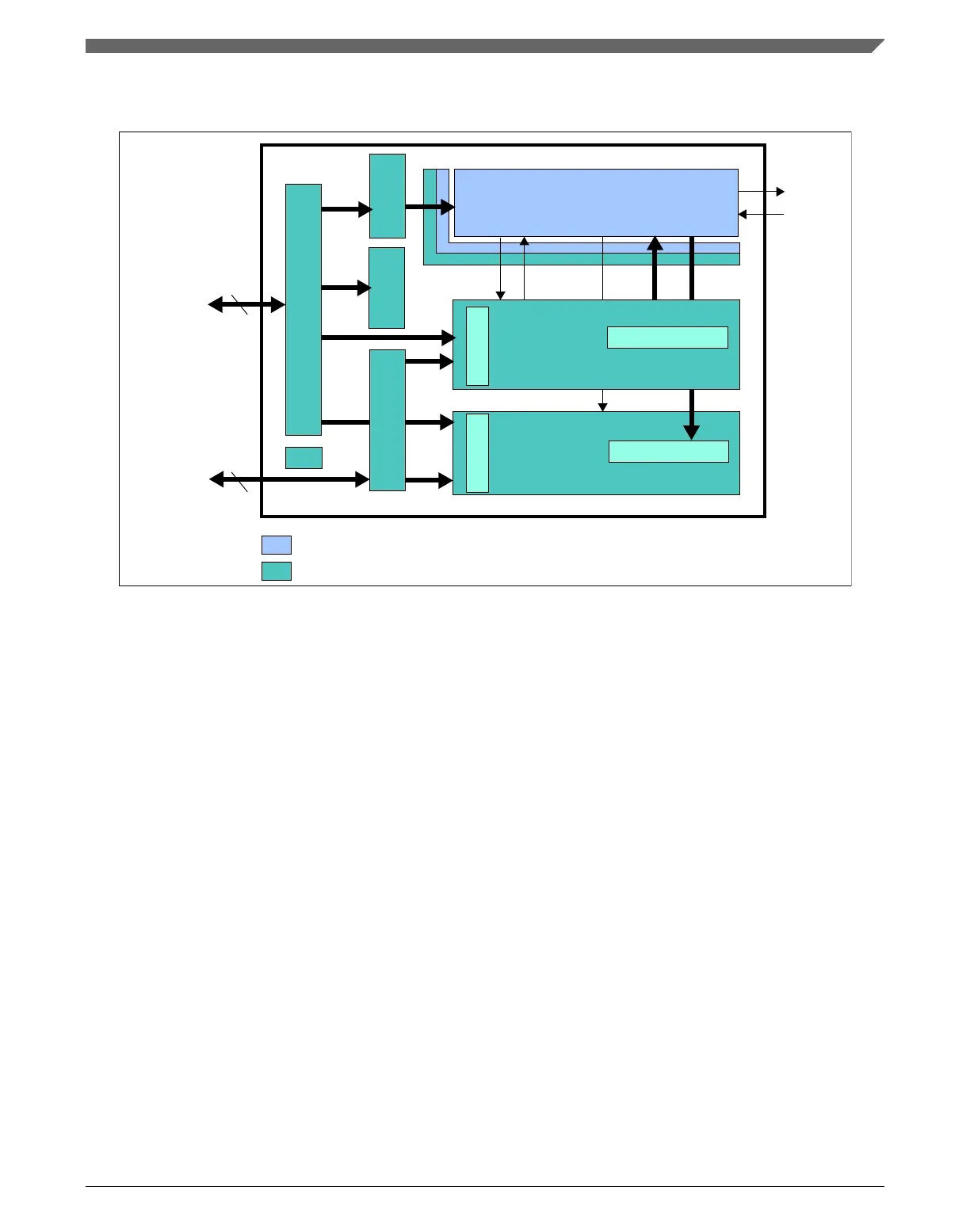
Figure 3-2. M_CAN Block Diagram
• CAN Core: CAN Protocol Controller and Rx/Tx Shift Register. Handles all ISO
11898-1 protocol functions. Supports 11-bit and 29-bit identifiers.
• Sync: Synchronizes signals from the Host clock domain to the CAN clock domain
and vice versa.
• Clk: Synchronizes reset signal to the Host clock domain and to the CAN clock
domain.
• Cfg and Ctrl: CAN Core related configuration and control bits.
• Interrupt and Timestamp: Interrupt control and 16-bit CAN bit time counter for
receive and transmit timestamp generation.
• Tx Handler: Controls the message transfer from the external Message RAM to the
CAN Core. A maximum of 32 Tx Buffers can be configured for transmission. Tx
buffers can be used as dedicated Tx Buffers, as Tx FIFO, part of a Tx Queue, or as a
combination of them. A Tx Event FIFO stores Tx timestamps together with the
corresponding Message ID. Transmit cancellation is also supported.
Chapter 3 Modular CAN (M_CAN)
MPC5777C Reference Manual Addendum, Rev. 1, 12/2015
Freescale Semiconductor, Inc. 25

 Loading...


