M_CAN_ILS field descriptions (continued)
Field Description
0 Interrupt assigned to M_CAN interrupt line 0
1 Interrupt assigned to M_CAN interrupt line 1
27
RF1NL
Rx FIFO 1 New Message Interrupt Line
0 Interrupt assigned to M_CAN interrupt line 0
1 Interrupt assigned to M_CAN interrupt line 1
28
RF0LL
Rx FIFO 0 Message Lost Interrupt Line
0 Interrupt assigned to M_CAN interrupt line 0
1 Interrupt assigned to M_CAN interrupt line 1
29
RF0FL
Rx FIFO 0 Full Interrupt Line
0 Interrupt assigned to M_CAN interrupt line 0
1 Interrupt assigned to M_CAN interrupt line 1
30
RF0WL
Rx FIFO 0 Watermark Reached Interrupt Line
0 Interrupt assigned to M_CAN interrupt line 0
1 Interrupt assigned to M_CAN interrupt line 1
31
RF0NL
Rx FIFO 0 New Message Interrupt Line
0 Interrupt assigned to M_CAN interrupt line 0
1 Interrupt assigned to M_CAN interrupt line 1
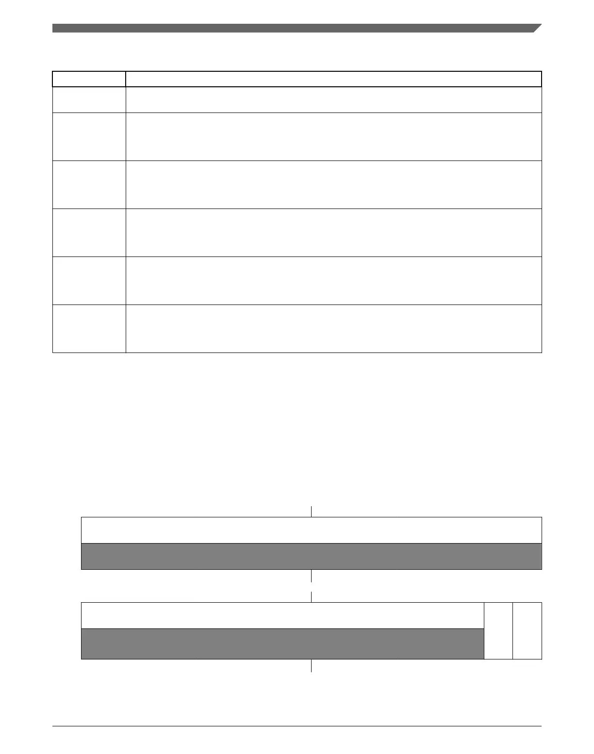
3.3.17 Interrupt Line Enable Register (M_CAN_ILE)
Each of the two interrupt lines to the CPU can be enabled / disabled separately by
programming bits EINT0 and EINT1.
Address: 0h base + 5Ch offset = 5Ch
Bit 0 1 2 3 4 5 6 7 8 9 10 11 12 13 14 15
R
0
W
Reset
0 0 0 0 0 0 0 0 0 0 0 0 0 0 0 0
Bit
16 17 18 19 20 21 22 23 24 25 26 27 28 29 30 31
R
0
EINT1
EINT0
W
Reset
0 0 0 0 0 0 0 0 0 0 0 0 0 0 0 0
Chapter 3 Modular CAN (M_CAN)
MPC5777C Reference Manual Addendum, Rev. 1, 12/2015
Freescale Semiconductor, Inc. 55

 Loading...


