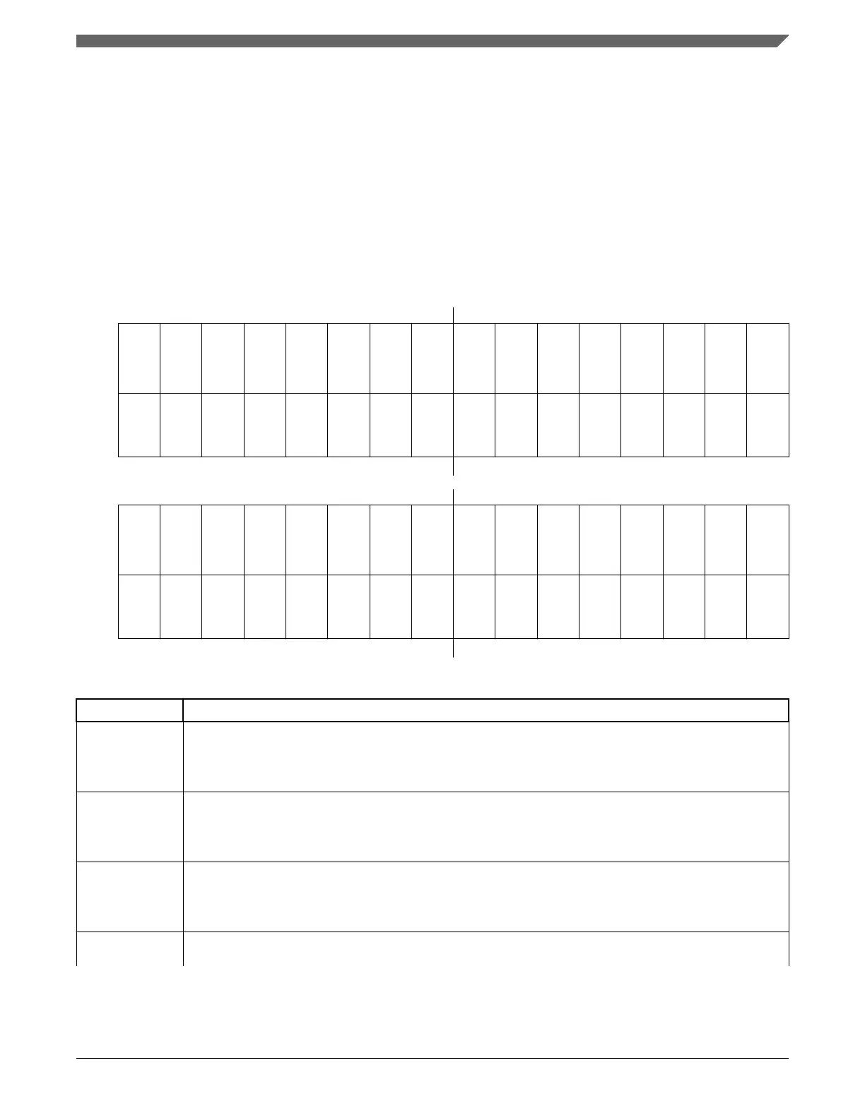
3.3.14 Interrupt Register (M_CAN_IR)
The flags are set when one of the listed conditions is detected (edge-sensitive). The flags
remain set until the CPU clears them. A flag is cleared by writing a 1 to the
corresponding bit position. Writing a 0 has no effect. A hard reset will clear the register.
The configuration of IE controls whether an interrupt is generated. The configuration of
ILS controls on which interrupt line an interrupt is signaled.
Address: 0h base + 50h offset = 50h
Bit 0 1 2 3 4 5 6 7 8 9 10 11 12 13 14 15
R
STE FOE
ACKE
BE
CRCE
WDI
BO
EW
EP
ELO BEU BEC
DRX
TOO
MRAF
TSW
W
w1c w1c w1c w1c w1c w1c w1c w1c w1c w1c w1c w1c w1c w1c
w1c
w1c
Reset
0 0 0 0 0 0 0 0 0 0 0 0 0 0 0 0
Bit
16 17 18 19 20 21 22 23 24 25 26 27 28 29 30 31
R
TEFL
TEFF
TEFW
TEFN
TFE TCF
TC
HPM
RF1L
RF1F
RF1W
RF1N
RF0L
RF0F
RF0W
RF0N
W
w1c w1c w1c w1c w1c w1c w1c w1c w1c w1c
w1c
w1c w1c w1c
w1c
w1c
Reset
0 0 0 0 0 0 0 0 0 0 0 0 0 0 0 0
M_CAN_IR field descriptions
Field Description
0
STE
Stuff Error
0 No Stuff Error detected
1 More than 5 equal bits in a sequence occurred
1
FOE
Format Error
0 No Format Error detected
1 A fixed format part of a received frame has the wrong format
2
ACKE
Acknowledge Error
0 No Acknowledge Error detected
1 A transmitted message was not acknowledged by another node
3
BE
Bit Error
Table continues on the next page...
Chapter 3 Modular CAN (M_CAN)
MPC5777C Reference Manual Addendum, Rev. 1, 12/2015
Freescale Semiconductor, Inc. 45

 Loading...


