3.3.12 Error Counter Register (M_CAN_ECR)
NOTE
When CCCR[ASM] is set, the CAN protocol controller does
not increment TEC and REC when a CAN protocol error is
detected, but CEL is still incremented.
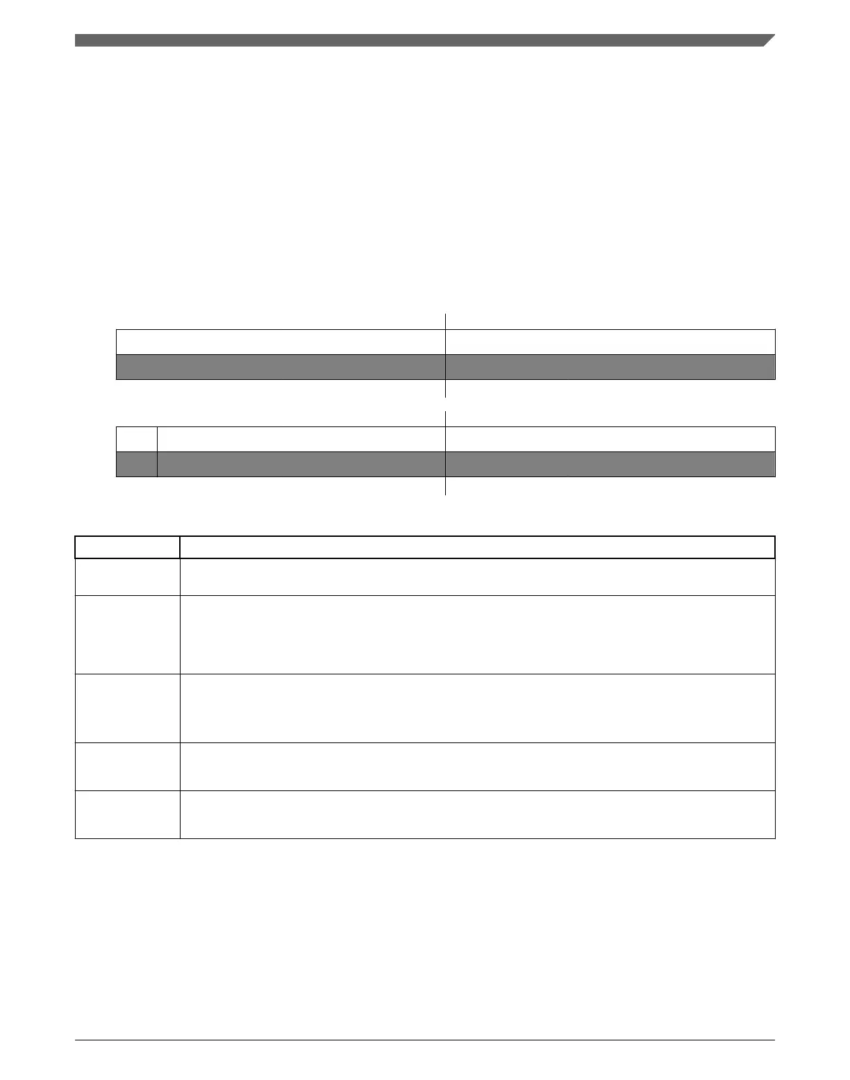
Address: 0h base + 40h offset = 40h
Bit 0 1 2 3 4 5 6 7 8 9 10 11 12 13 14 15
R
0 CEL
W
Reset
0 0 0 0 0 0 0 0 0 0 0 0 0 0 0 0
Bit
16 17 18 19 20 21 22 23 24 25 26 27 28 29 30 31
R
RP REC TEC
W
Reset
0 0 0 0 0 0 0 0 0 0 0 0 0 0 0 0
M_CAN_ECR field descriptions
Field Description
0–7
Reserved
This field is reserved.
This read-only field is reserved and always has the value 0.
8–15
CEL
CAN Error Logging
The counter is incremented each time when a CAN protocol error causes the Transmit Error Counter or
the Receive Error Counter to be incremented. It is reset by read access to CEL. The counter stops at
0xFF; the next increment of TEC or REC sets interrupt flag IR[ELO].
16
RP
Receive Error Passive
0 The Receive Error Counter is below the error passive level of 128
1 The Receive Error Counter has reached the error passive level of 128
17–23
REC
Receive Error Counter
Actual state of the Receive Error Counter, values between 0 and 127.
24–31
TEC
Transmit Error Counter
Actual state of the Transmit Error Counter, values between 0 and 255.
Chapter 3 Modular CAN (M_CAN)
MPC5777C Reference Manual Addendum, Rev. 1, 12/2015
Freescale Semiconductor, Inc. 41

 Loading...


