45762101TH Rev.1
4-23
(6) Remove the screw (silver-colored M4)
⑩
to remove the Plate-FG
⑪
.
(7) Remove five screws (silver-colored)
⑫
to remove the SU-Board
⑬
.
(8) Remove the screw (black-colored, L=8mm)
⑭
to remove the Plate-USB
⑮
.
And remove two screws (silver-colored, L=12mm)
⑯
to remove the cord-
USB
⑰
.
And remove the core
⑱
from Cord-USB
⑰
. (two claws)
(9) Remove the screw (silver-colored M4)
⑲
to remove the cord-FG
⑳
.
(10) Remove three screws (black-colored, L=8mm)
to remove the Plate-Board
(SU)
.
(11) Remove two screws (black-colored, L=10mm)
to remove the Cover-Assy-
LF
.
(12) Remove four s crews (black-colored, L =10mm)
to remove the Cover-
Hinge-L
and the Plate-Hinge-L (Caulking)
.
(13) Remove seven screws (black-colored, L=10mm M4 )
to remove the Cam-
hinge
.
Note! (to assemble)
1. Since a cable will be pushed by Plate-Shield (SU), please place
downward.
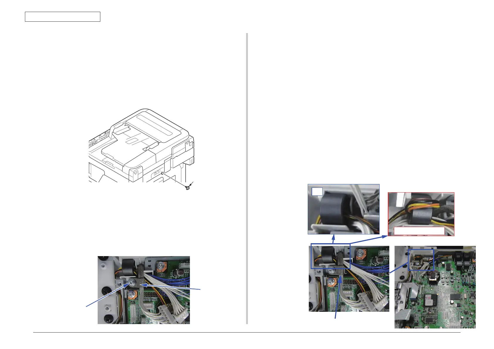
4.2.8.13 Frame-assy-FB
Note! • It exchanges it detaching the scanner unit from the MFP when the
SU-board is exchanged.
• If replaced new board, update Firmware according to Chapter 9.3.
It is necessary to take the synchronization of the firmware version of
SU board and CU board.
(1) Remove the screw (silver-colored M4)
①
.
(2)
Remove four screws (black-colored, L=10mm)
②
to remove the Cover Bottom
③
.
(3) Remove Plate-FG (FAX)
④
from Cover Bottom
③
.
(4) Remove five screws (silver-colored)
⑤
and five screws (black-colored,
L=8mm)
⑥
to remove the Plate-Shield (SU)
⑦
.
(5) Remove the screw (silver-colored)
⑧
to remove the Clamp
⑨
. An d
remove all SU-Board cables.
NG(The cable upward)
OK
The cable with the shield should be