45762101TH Rev.1
4-37
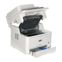
4.2.18 Fuser Assy
Note! Replace the Fuser-Assy by Assy unit.
It is forbidden for disassembling the Fuser-Assy, also, reusing the
disassembled Fuser-Assy.
(1) Remove the Frame Assy TR. (Refer to 4.2.11)
(2) Remove the Scanner unit. (Refer to 4.2.8)
(3) Remove the Cover Assy Stacker. (Refer to 4.2.16)
(4) Remove the Guide Cable. (Refer to 4.2.14)
(5) Remove the PWR unit-ACDC Switch. (Refer to 4.2.4)
(6) Remove the Plate Bracket (CU). (Refer to 4.2.14)
(7) Remove the Plate Base (PWU). (Refer to 4.2.14)
(8) Remove two screws (Silver)
①
. Remove the Plate-Duct-Assy
②
.
(9) Remove the two screws (Silver)
③
and lift off Fuser-Assy
④
after
disconnecting every cable from it.
(10 ) Remove the Lever-Link-Fuser
⑤
.(Both side)
(11) Assembling is performed by the inverse procedure with removing.
Note!
1. Fuser-Assy
④
may be really hot, beware of handling.
2. Beware of not to touch the DC motor inattentively (Do not rotate the motor).
3. Install the Fuser-Assy
④
and Plate-Duct-Assy
②
carefully to avoid
cables from being caught.
4. Beware of not to damage the FFC cable when disconnect the thick cable
from Plate-Side-R-Assy.
5. Disconnect the FFC cable, when disconnect the thick cable. Beware
of not to harflock the FFC cable when connect the FFC cable.
①
①
②
A square hole to draw the thick cable
Thick cable
Thin cable
③
③
⑤
⑤
④
④
View A
View A