2-42 Service Manual
Operator panel service check
Warning: Replace one of the following components, and perform a POR before replacing a second
component. Never replace both of the components without performing a POR after installing each
one, or the printer will be rendered inoperable:
• Operator panel assembly
• Controller board
Warning: Never install and remove components listed above as a method of troubleshooting components.
Once a component has been installed in a printer, and the printer is powered on, it cannot be
used in another printer. It must be returned to the manufacturer.
One or more operator panel buttons fail
Operator panel display blank, five beeps
Service tip: The printer has detected a problem with the controller board, the operator panel assembly cable
(part of the front cover assembly), or the operator panel assembly if POST does not complete. The printer emits
five beeps, and sticks in a continuous pattern until the printer is turned off.
Step Questions / actions Yes No
1 Run the Button Test. See “Button Test” on
page 3-13 in Diagnostics Menu.
Did any of the buttons fail the test?
Replace the operator panel
assembly. See “Operator
panel removal” on
page 4-98.
Go to step 2.
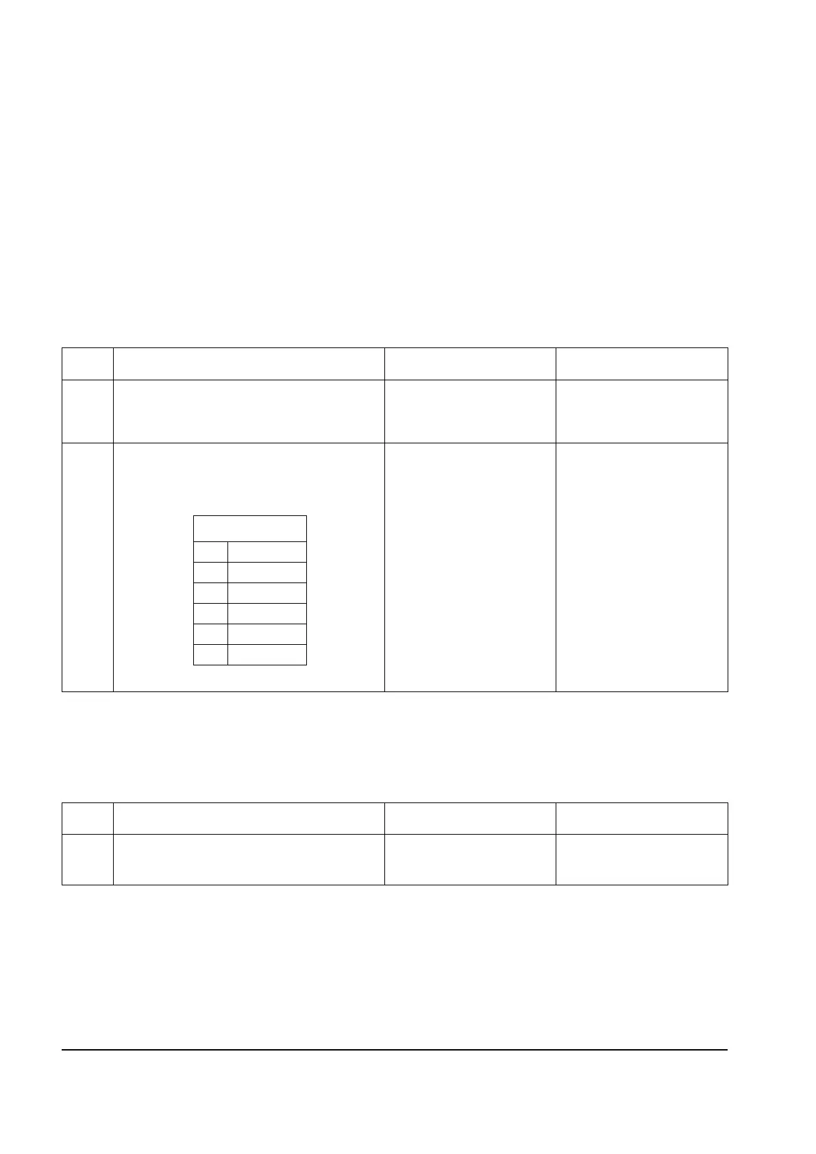
2
Turn the printer off, and remove the rear
shield. “Rear shield removal” on page 4-7.
Disconnect the operator panel assembly cable
at JOPP1 on the controller board. Turn on the
printer, and verify the following voltages:
Are the voltage values approximately correct?
Replace the operator panel.
See “Operator panel
removal” on page 4-98.
If the problem is not
resolved, replace the
operator panel cable. See
“Op panel cable” on
page 4-101
Replace the controller
board. See “Controller
board removal” on
page 4-18.
Step Questions / actions Yes No
1 Is the operator panel assembly cable properly
installed at controller board JOPP1 and at the
operator panel assembly?
Go to step 2. Reinstall the cable.
JOPP1
Pin Voltage
2 +5 V dc
4 Ground
5 +5 V dc
6 +3.3 V dc
7 Ground
Y112730-2
 Loading...