99
Programming Devices Section 3-6
One-to-many
Communications
The following table shows the connections methods for communications
between one personal computer and many PCs.
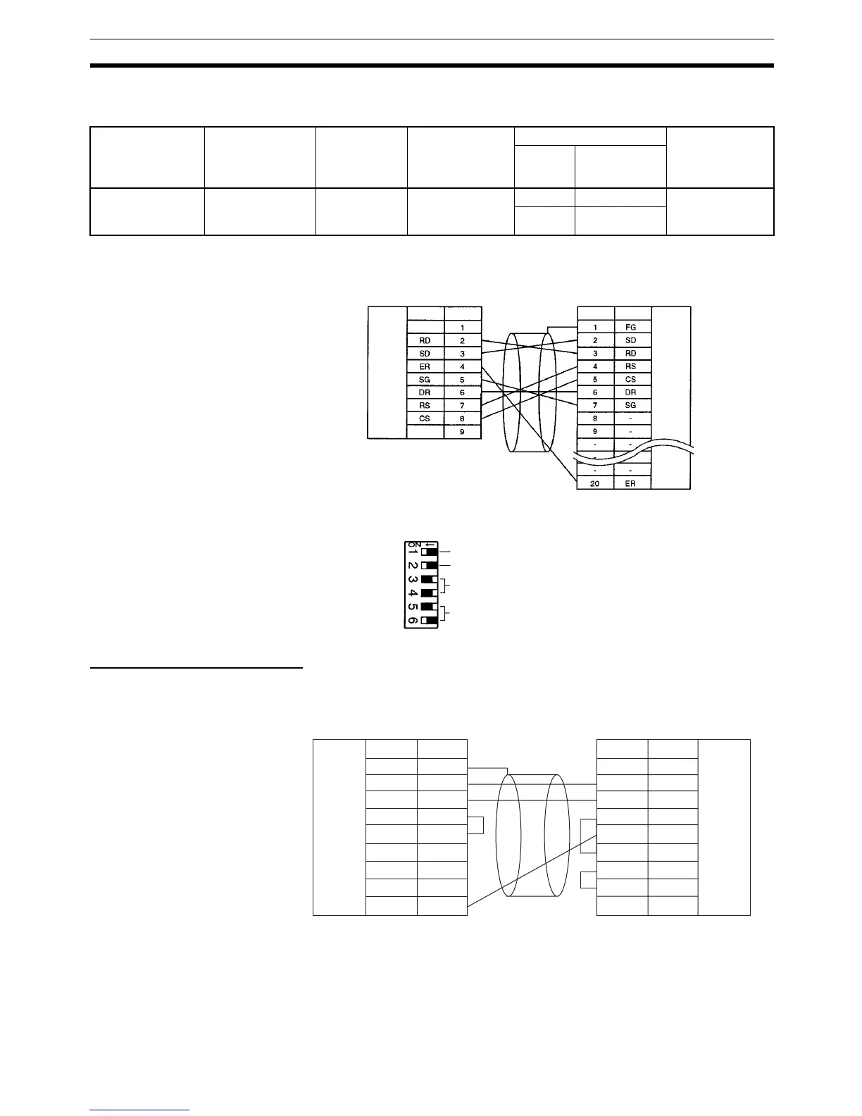
Prepare the RS-232C cable between the 3G2A9-AL004-E Link Adapter and
the computer as shown below.
The DIP switch settings of the NT-AL001-E Link Adapter are shown below.
Preparing RS-232C Cables
Connecting to
CX-Programmer
When connecting the RS-232C port to the CX-Programmer, set the communi-
cations mode to Host Link mode and connect in the following way.
When preparing an RS-232C cable to be connected to the RS-232C port, use
the following connector cables.
Serial
communications
mode
RS-232C cable at
the personal
computer
RS-232C-to-
RS422A/485
Converting
Link Adapter
RS-422A/485 -
to-RS-232C
Converting Link
Adapter
Connecting cable Port at PC
Length Model
number
Host Link Make your own
cable (See
below.)
3G2A9-
AL004-E
NT-AL001-E 0.7 m XW2Z-070T-1 RS-232C port
(D-Sub, 9-pin,
female)
2 m XW2Z-200T-1
3G2A9-AL004-E Link Adapter
IBM PC/AT or compatible
Signal
Pin No.
RS-232C
interface
RS-232C
interface
(D-sub, 25-pin, male)
(D-sub, 9-pin, female)
SignalPin No.
---
Always ON
Turn ON at end of transmission path and turn OFF
elsewhere.
Turn both pins OFF for 4-wire connection.
Turn OFF pin 5 and turn ON pin 6 for RS-232C
CTS control.
CQM1H-series CPU Unit
IBM PC/AT or compatible
Signal Pin No. SignalPin No.
RS-232C
interface
RS-232C
interface
(D-sub, 9-pin, male)
(D-sub, 9-pin, female)
FG 1
SD 2
RD 3
RS 4
CS 5
5V 6
DR 7
ER 8
SG 9
1CD
2RD
3SD
4ER
5SG
6DR
7RS
8CS
9CI

 Loading...


