961
Basic I/O Unit Instructions Section 3-23
The inputs and outputs can be connected to the following kinds of Basic I/O
Units and High-density I/O Units as long as they are not mounted in a SYS-
MAC BUS Remote I/O Rack.
• 4-digit display: Transistor Output Units with 8 or more output points
• 8-digit display: Transistor Output Units with 16 or more output points
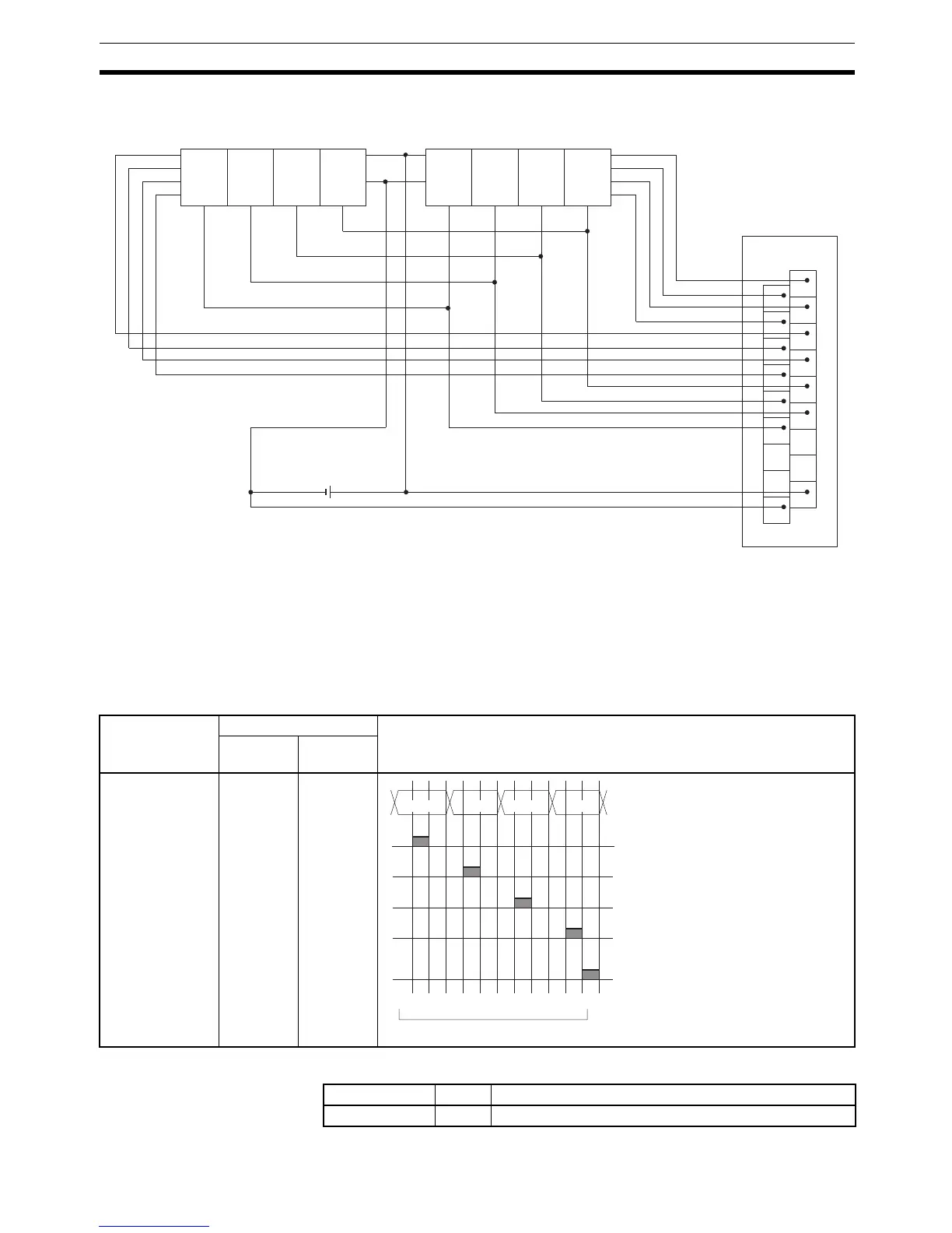
Timing Chart
Flags
1
3
5
7
9
11
13
15
COM
0
2
4
6
8
10
12
14
DC
OD212
D
0
D
1
D
2
D
3
V
DD
(+)
V
SS
(0)
LE3 LE2 LE1 LE0
D
0
D
1
D
2
D
3
V
DD
(+)
V
SS
(0)
LE3 LE2 LE1 LE0
7-segment display
Leftmost 4 digits Rightmost 4 digits
Output Unit
Function Bit(s) in O Output status (Data and latch logic depends on C)
(4 digits, 1
block)
(4 digits, 2
blocks)
Latch output 2
Latch output 3
One Round Flag
Latch output 1
Latch output 0
Data output
06
07
08
05
04
00 to 03
10
11
12
09
08
00 to 03
04 to 07
10
0
10
1
10
2
10
3
1 2 3 4 5 6 7 8 9 10 11 12 1
12 cycles required to complete one round
Note 0 to 3: Data output for word S
4 to 7: Data output for word S+1
Name Label Operation
Error Flag ER OFF