908
Step Instructions Section 3-22
Flags
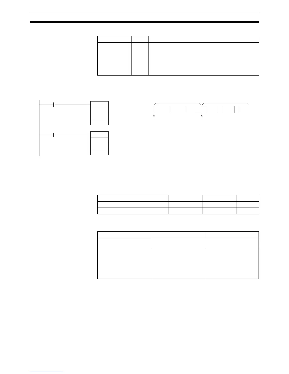
Example When CIO 000000 turns ON in the following programming example,
PWM(891) starts pulse output from pulse output 0 at 200 Hz with a duty factor
of 50%. When CIO 000001 turns ON, the duty factor is changed to 25%.
3-22 Step Instructions
This section describes Step Instructions, which are used to set up break
points between sections in a large program so that the sections can be exe-
cuted as units and reset upon completion.
In CS/CJ-series PLCs, STEP(008)/SNXT(009) can be used together to create
step programs.
Name Label Operation
Error Flag ER ON if the specified range for P, F, or D is exceeded.
ON if pulses are being output using ORG(889) for the
specified port.
ON if PWM(891) is executed in an interrupt task when an
instruction controlling pulse output is being executed in a
cyclic task.
@PWM
#0000
#07D0
#0032
000000
@PWM
#0000
#07D0
#0019
000001
CIO 000000 ON CIO 000001 ON
Pulse output 0
Frequency: 200.0 Hz
Duty factor: 50%
Pulse output 0
Frequency: 200.0 Hz
Duty factor: 25%
Duty factor: 50% Duty factor: 25%
Instruction Mnemonic Function code Page
STEP DEFINE STEP 008 909
STEP START SNXT 009 909
Instruction Operation Diagram
SNXT(009): STEP START Controls progression to the
next step of the program.
Corresponds
STEP(008): STEP DEFINE Indicates the start of a
step. Repeats the same
step program until the con-
ditions for progression to
the next step are estab-
lished.
Corresponds