940
Basic I/O Unit Instructions Section 3-23
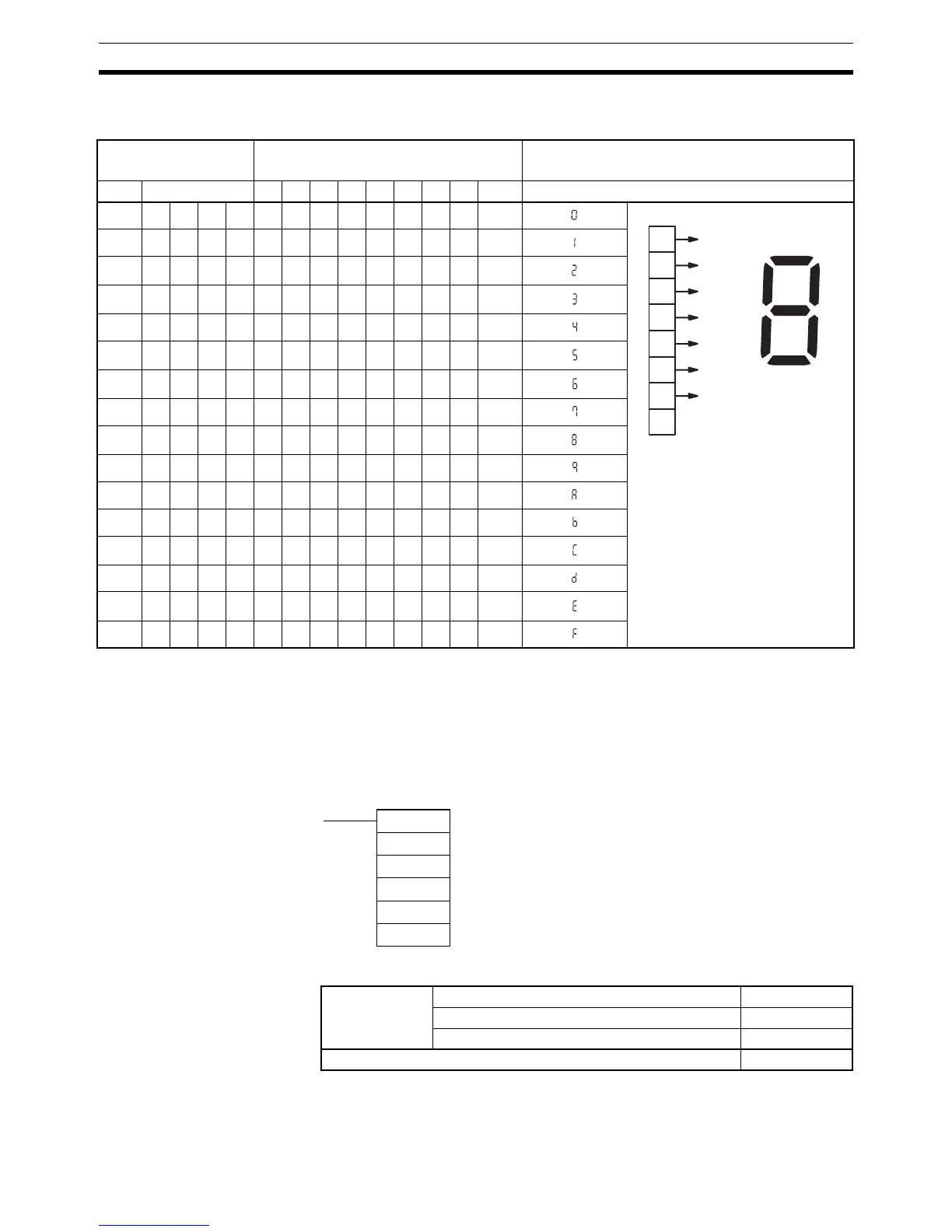
7-segment Data The following table shows the data conversions from a hexadecimal digit (4
bits) to 7-segment code (8 bits).
3-23-5 DIGITAL SWITCH INPUT – DSW(210)
Purpose Reads the value set on a external digital switch (or thumbwheel switch) con-
nected to an I/O Unit and stores the 4-digit or 8-digit value in the specified
words.
This instruction is supported only by CS/CJ-series CPU Unit Ver. 2.0 or later.
Ladder Symbol
Variations
Original data Converted code (segments) Display
Original data
Digit Bits –gfedcbaHex
0 0000001111113F
1 00010000011006
2 0010010110115B
3 0011010011114F
4 01000110011066
5 0101011011016D
6 0110011111017D
7 01110010011127
8 1000011111117F
9 1001011011116F
A 10100111011177
B 1011011111007C
C 11000011100139
D 1101010111105E
E 11100111100179
F 11110111000171
1
1
1
1
1
1
1
0
g
fb
c
d
e
a
a
b
c
d
e
f
g
LSB
MSB
DSW(210)
I
O
D
C1
C2
I: Input word
O: Output word
D: First result word
C1: Number of digits
C2: System word
Variations Executed Each Cycle for ON Condition DSW(210)
Executed Once for Upward Differentiation Not supported.
Executed Once for Downward Differentiation Not supported.
Immediate Refreshing Specification Not supported.