1053
Network Instructions Section 3-25
6. The maximum node number depends on the network being used. For a
Controller Link, the allowed range is 00 to 20 hexadecimal (0 to 32). Set
the source node number to 00 to transmit within the local node.
7. Refer to
Automatic Allocation of Communications Ports on page 1032 for
details on using automatic allocation of the communications port number
(logical port).
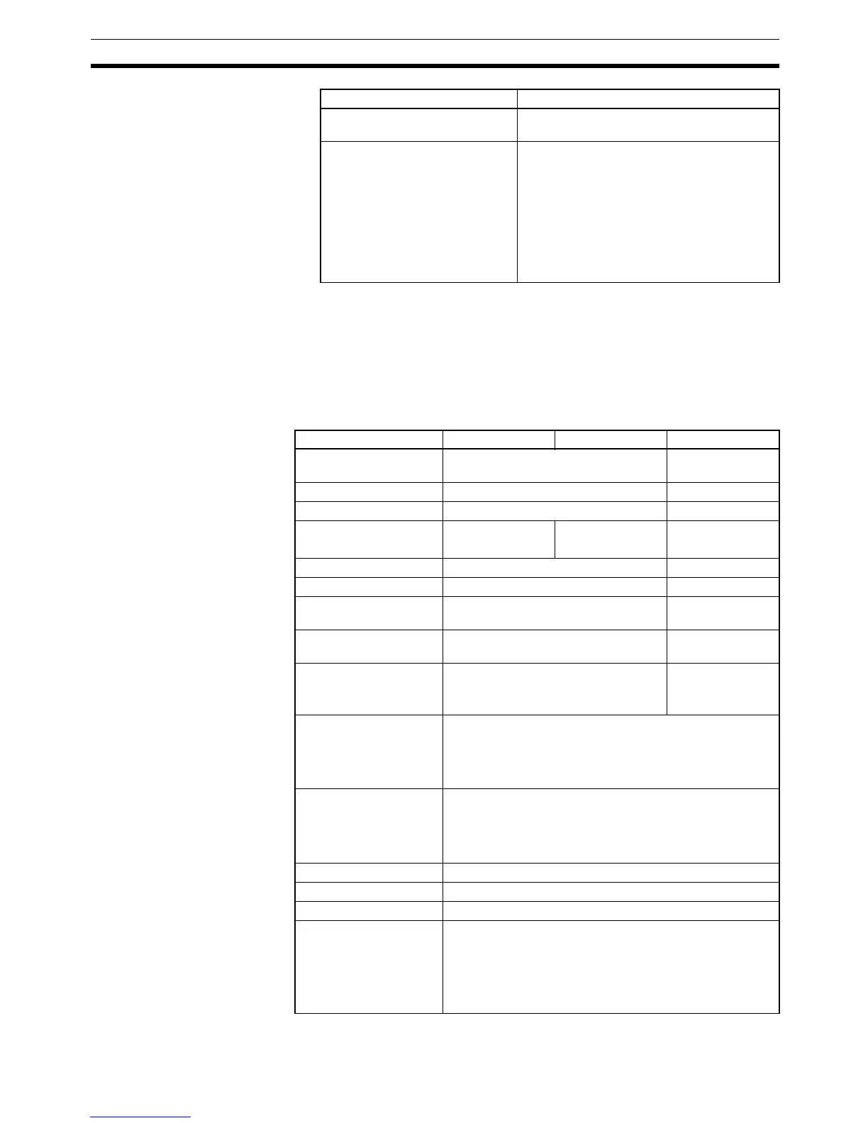
Operand Specifications
Unit connected to network (not
necessary to specify Unit)
FE hex
Direct specification of the serial
port’s unit address
Serial Communications Unit ports
Port 1: 80 hex + 4 × unit number
Port 2: 81 hex + 4 × unit number
Serial Communications Board ports
Port 1: E4 hex (228 decimal)
Port 2: E5 hex (229 decimal)
CPU Unit ports
Peripheral port: FD hex (253 decimal)
RS-232C port: FC hex (252 decimal)
Unit Unit address setting
Area S D C
CIO Area CIO 0000 to CIO 6143 CIO 0000 to
CIO 6139
Work Area W000 to W511 W000 to W507
Holding Bit Area H000 to H511 H000 to H507
Auxiliary Bit Area A000 to A447
A448 to A959
A448 to A959 A000 to A443
A448 to A955
Timer Area T0000 to T4095 T0000 to T4091
Counter Area C0000 to C4095 C0000 to C4091
DM Area D00000 to D32767 D00000 to
D32763
EM Area without bank E00000 to E32767 E00000 to
E32763
EM Area with bank En_00000 to En_32767
(n = 0 to C)
En_00000 to
En_32763
(n = 0 to C)
Indirect DM/EM
addresses in binary
@ D00000 to @ D32767
@ E00000 to @ E32767
@ En_00000 to @ En_32767
(n = 0 to C)
Indirect DM/EM
addresses in BCD
*D00000 to *D32767
*E00000 to *E32767
*En_00000 to *En_32767
(n = 0 to C)
Constants ---
Data Registers ---
Index Registers ---
Indirect addressing
using Index Registers
,IR0 to ,IR15
–2048 to +2047, IR0 to –2048 to +2047, IR15
DR0 to DR15, IR0 to IR15
,IR0+(++) to ,IR15+(++)
,–(– –)IR0 to, –(– –)IR15