1083
Network Instructions Section 3-25
Operand Specifications
Description Sends the explicit message command with service code 10 hex (stored in the
range of words beginning at S+2) to the node address specified in S+1, via
the Communications Unit with the FINS unit address specified in bits 00 to 07
of C. When the response to the explicit message is received, it is stored in the
range of words beginning at D+2.
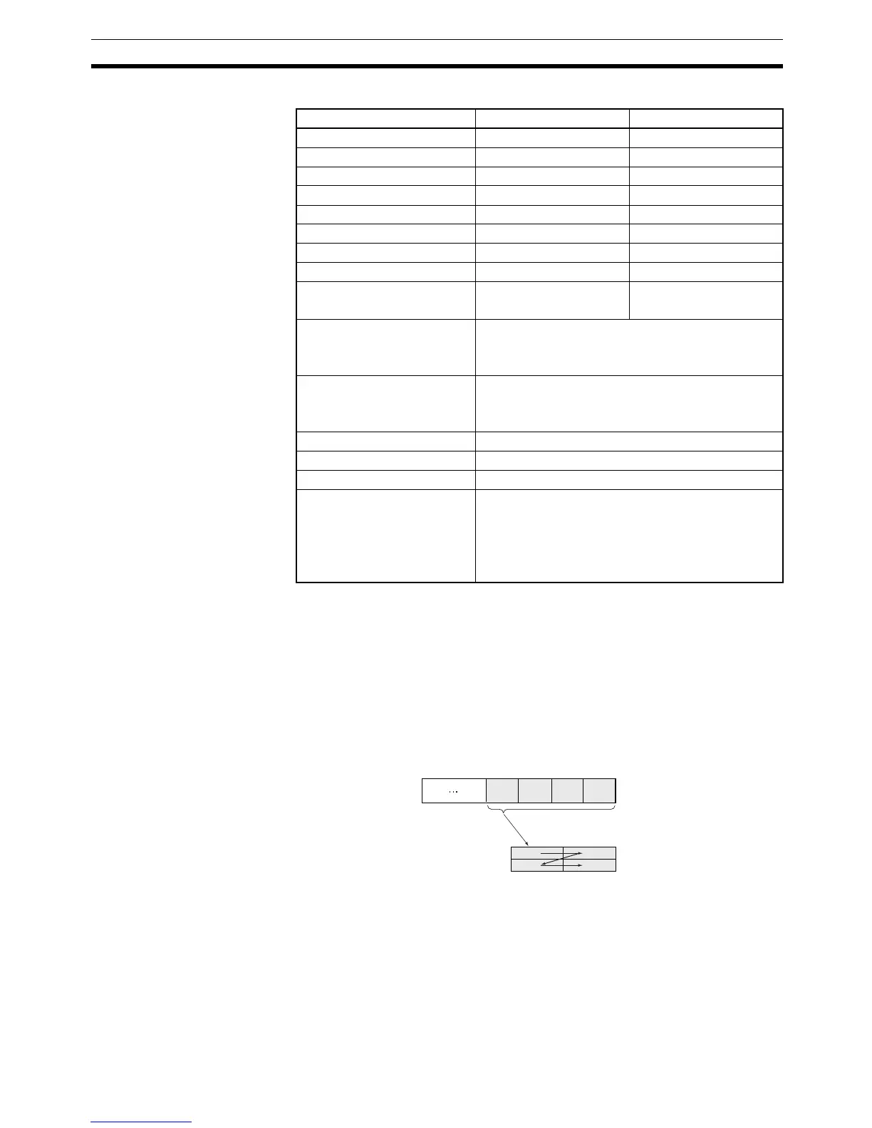
The setting in bits 12 to 15 of C (0 or 8 hex) determines the byte-order of the
service data stored at S+5.
• Storing Data from the Leftmost Byte
Set bits 12 to 15 of C to 0 hex.
Area S C
CIO Area CIO 0000 to CIO 6143 CIO 0000 to CIO 6141
Work Area W000 to W511 W000 to W509
Holding Bit Area H000 to H511 H000 to H509
Auxiliary Bit Area A000 to A959 A000 to A957
Timer Area T0000 to T4095 T0000 to T4093
Counter Area C0000 to C4095 C0000 to C4093
DM Area D00000 to D32767 D00000 to D32765
EM Area without bank E00000 to E32767 E00000 to E32765
EM Area with bank En_00000 to En_32767
(n = 0 to C)
En_00000 to En_32765
(n = 0 to C)
Indirect DM/EM addresses in
binary
@ D00000 to @ D32767
@ E00000 to @ E32767
@ En_00000 to @ En_32767 (n = 0 to C)
Indirect DM/EM addresses in
BCD
*D00000 to *D32767
*E00000 to *E32767
*En_00000 to *En_32767 (n = 0 to C)
Constants ---
Data Registers ---
Index Registers ---
Indirect addressing using
Index Registers
,IR0 to ,IR15
–2048 to +2047, IR0 to –2048 to +2047, IR15
DR0 to DR15, IR0 to IR15
,IR0+(++) to ,IR15+(++)
,–(– –)IR0 to, –(– –)IR15
A
15
AS+5
S+6
B
CD
08 07 00
BCD
Frame (order of data in line)
Stored from leftmost byte.
Note: A, B, C, and D represent bytes of data.
Data
area