1152
Failure Diagnosis Instructions Section 3-30
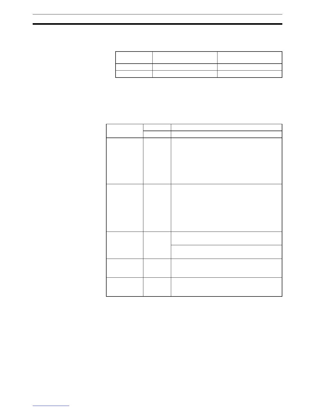
4. The following table shows how the IOM Hold Bit affects the status of I/O
memory and the status of outputs on Output Units after a fatal system error
has been generated with FALS(007).
Note Unlike user-defined fatal errors, system errors generated by FALS(007) will
clear I/O memory if the IOM Hold Bit is OFF. The following areas will be
cleared: CIO Area, Work Area, Timer Flags and PVs, Index Registers, and
Data registers.
The following table shows how to specify error codes and error details in S
and S+1.
IOM Hold Bit
(A50012)
Status of I/O memory Status of outputs on Output
Units
ON Retained OFF
OFF Cleared OFF
Error name S S+1
Error code Error details
Memory Error 80F1 hex • Bits 00 to 09: Memory Error Location
Bit 00: User program
Bit 04: PLC Setup
Bit 05: Registered I/O table
Bit 07: Routing table
Bit 08: CPU Bus Unit Setup
Bit 09: Memory Card transfer error
• Bits 10 to 15: Invalid
I/O Bus Error 80C0 hex • Bits 00 to 07: Slot number where the I/O Bus error
occurred
Slot 0 to 9: 00 to 09 hex
Slot unknown: 0F hex
• Bits 08 to 15: Rack number where the I/O Bus
error occurred
Slot 0 to 7: 00 to 07 hex
Rack unknown: 0F hex
Unit Number
Duplication
Error
80E9 hex CPU Bus Unit’s duplicated unit number
0000 to 000F hex
Special I/O Unit’s duplicated unit number
8000 to 805F hex
Rack Number
Duplication
Error
80EA hex Duplicated Rack number (overlapping word alloca-
tions)
0000 to 0006 hex
Fatal Inner
Board Error
82F0 hex Error Cause
Bits 00 to 03: Error defined by Inner Board
Bits 04 to 15: Invalid