1157
Failure Diagnosis Instructions Section 3-30
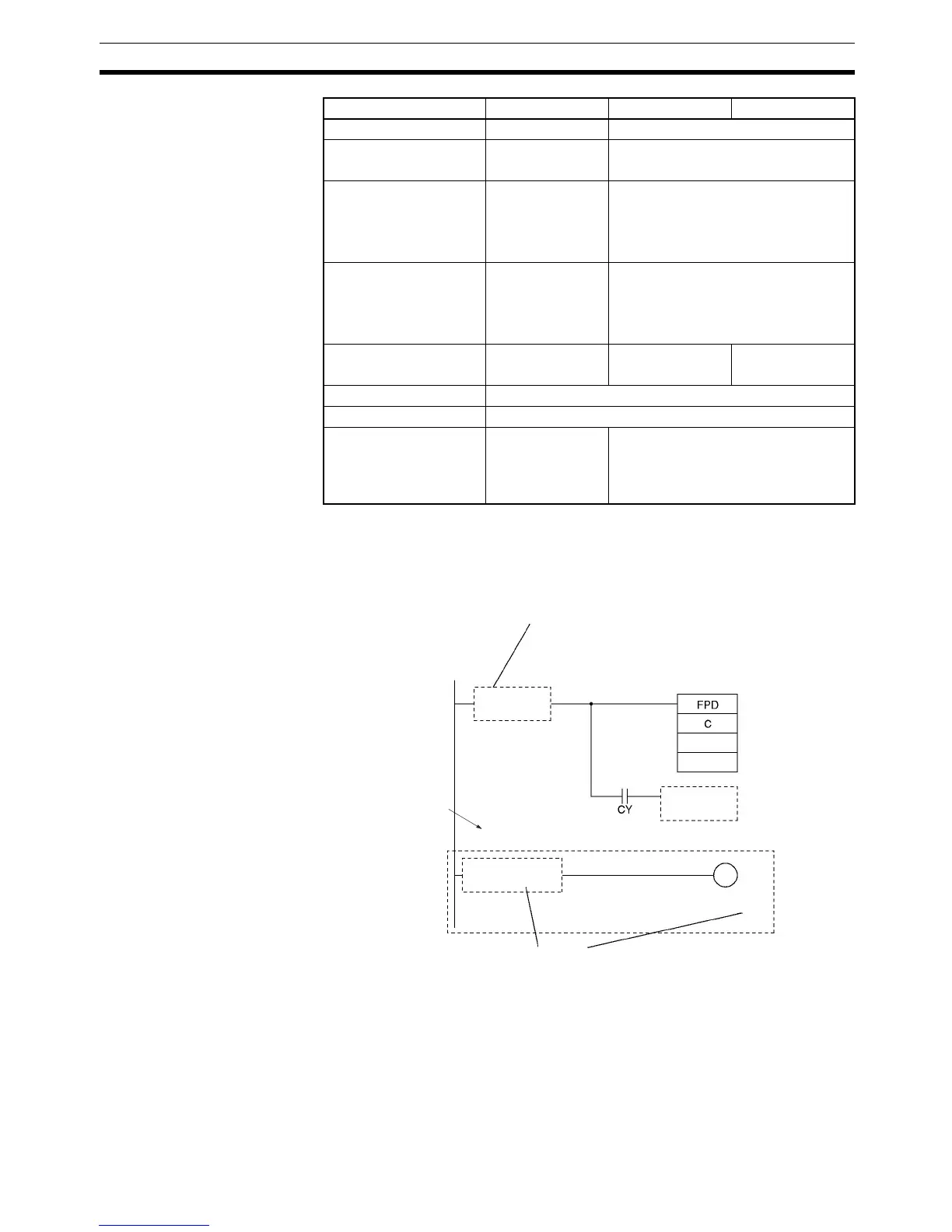
Description FPD(269) performs time monitoring and logic diagnosis. The time monitoring
function generates a non-fatal error with the specified FAL number if the diag-
nostic output is not turned ON within the specified monitoring time. The logic
diagnosis function indicates which input is preventing the output from being
turned ON.
Note *The logic diagnosis block begins with the first LD (not LD TR) or LD NOT
instruction after FPD(269) and ends with the first OUT (not OUT TR) or other
right-hand instruction.
EM Area without bank --- E00000 to E32767
EM Area with bank --- En_00000 to En_32767
(n = 0 to C)
Indirect DM/EM
addresses in binary
--- @ D00000 to @ D32767
@ E00000 to @ E32767
@ En_00000 to @ En_32767
(n = 0 to C)
Indirect DM/EM
addresses in BCD
--- *D00000 to *D32767
*E00000 to *E32767
*En_00000 to *En_32767
(n = 0 to C)
Constants Specified values
only
#0000 to #270F
(binary)
---
Data Registers ---
Index Registers ---
Indirect addressing
using Index Registers
--- ,IR0 to ,IR15
–2048 to +2047 ,IR0 to –2048 to
+2047 ,IR15
DR0 to DR15, IR0 to IR15
Area C T R
T
R
Diagnostic output B
Logic diagnosis function
Time monitoring function:
Starts timing when execution condition A goes ON.
Generates a non-fatal error if output B isn't turned
ON within the monitoring time.
Execution
condition A
Error-processing
block (optional)
Logic diagnosis block*
Next instruction block
Logic diagnosis
execution condition C
Determines which input in C prevents
output B from going ON.