1160
Failure Diagnosis Instructions Section 3-30
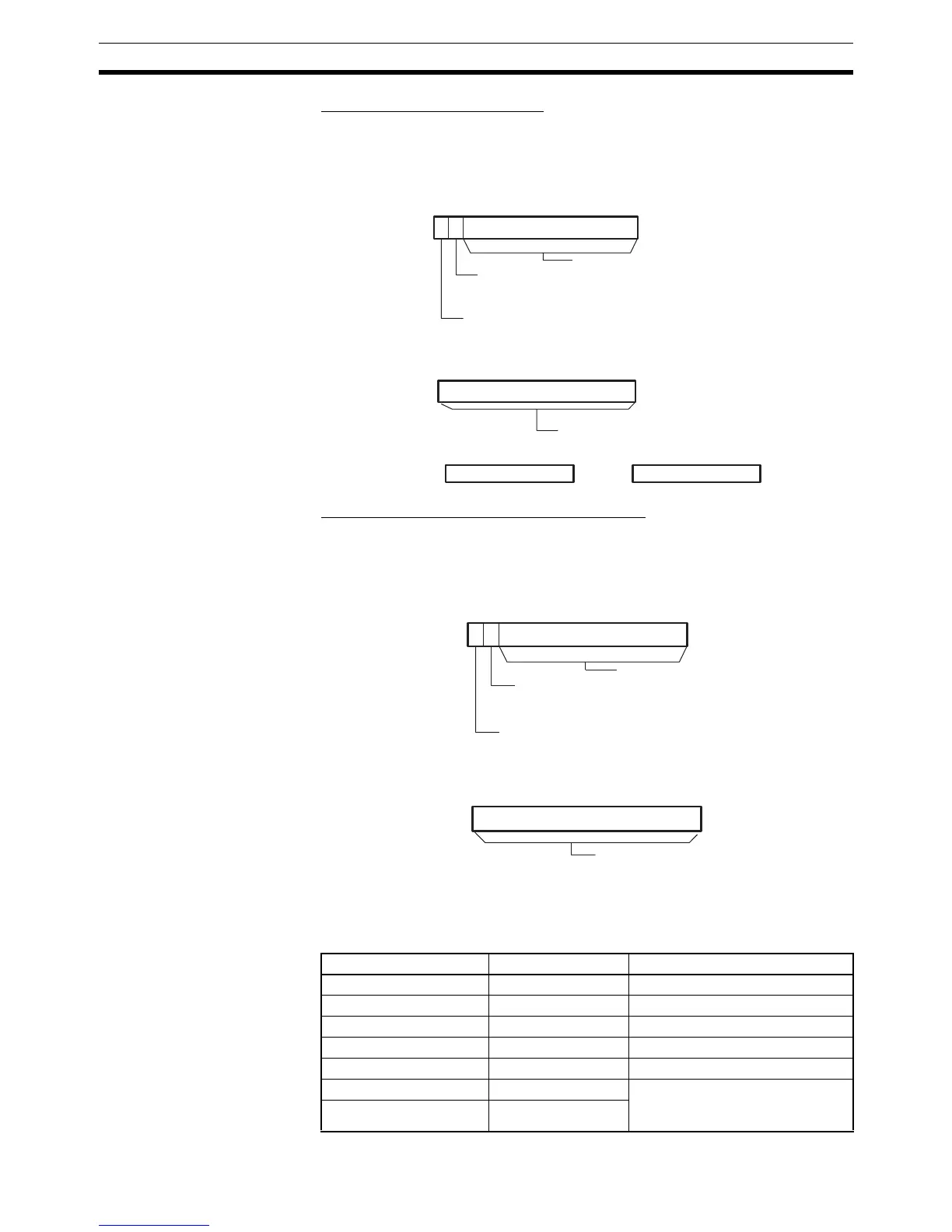
Bit Address Output (C=0@@@)
When the leftmost digit of C is set to 0, the 8-digit hexadecimal PLC memory
address of the input bit is output to R+2 and R+3. R contains two flags which
indicate whether an input bit has been found and whether it is used in a nor-
mally open or normally closed input condition.
Bit Address and Message Output (C=8
@@@)
When the leftmost digit of C is set to 8, the ASCII address of the input bit is
output to R+2 to R+4. R contains two flags which indicate whether an input bit
has been found and whether it is used in a normally open or normally closed
input condition.
Register words R+2 to R+4 indicate the address of the input which prevented
the diagnostic output from being turned ON. The bit address is output to these
words in ASCII. The following table shows the ASCII representations for each
area.
Area ASCII text Notes
Auxiliary Area A00000 to A95915 ---
Holding Area H00000 to H51115 ---
Work Area W00000 to W51115 ---
CIO Area 000000 to 665515 ---
Task Flags TK0000 to TK0031 ---
Timer Area _T0000 to _T4095 The “_” represents an ASCII
space.
(Character code 20.)
Counter Area _C0000 to _C4095
15
014
R
13
15
R+2 R+3
R+1
0
Not possible to use.
Input type
0: Normally open
1: Normally closed
Bit Address Found Flag
0: Not found yet
1: Bit address found
Not possible to use.
15 014
R
13
15
0
R+1
Not possible to use.
Input type
0: Normally open
1: Normally closed
Bit Address Found Flag
0: Not found yet
1: Bit address found
Not possible to use.