254
Timer and Counter Instructions Section 3-6
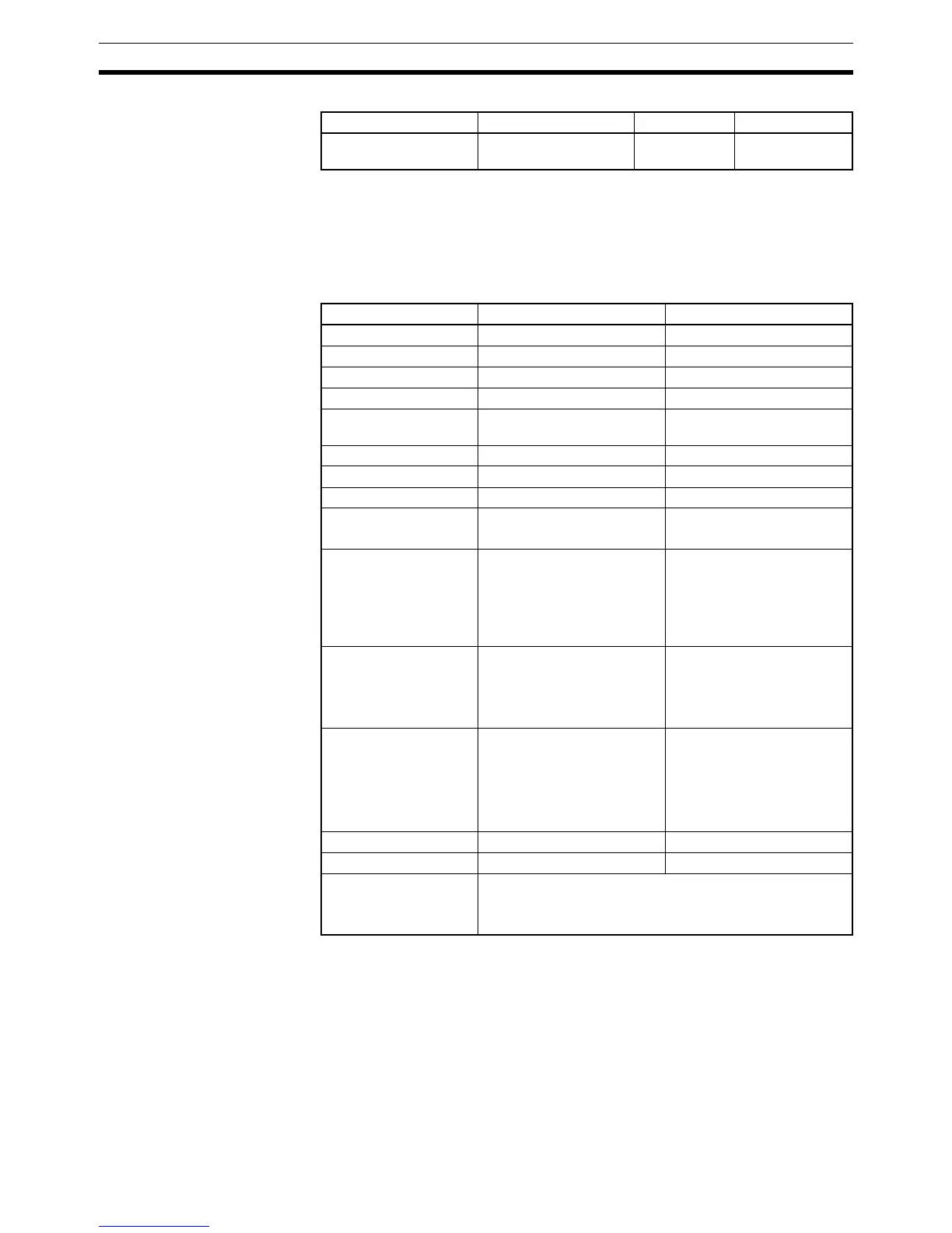
Applicable Program Areas
Operands N: Timer Number
The timer number must be between 0000 and 0015 (decimal).
S: Set Value
The set value must be between #0000 and 9999 (BCD).
Operand Specifications
Note In CJ1-H-R CPU Units other than those with unit version 4.1, N can be set to
between 0 and 4,095 decimal. In CJ1-H-R CPU Units with unit version 4.1, N
can be set only to between 16 and 4095 decimal. For details, refer to
Refresh-
ing of TMHH(540) and TMHHX(552) PVs and Completion Flags
on page 256.
Description When the timer input is OFF, the timer specified by N is reset, i.e., the timer’s
PV is reset to the SV and its Completion Flag is turned OFF.
When the timer input goes from OFF to ON, TMHH(540)/TMHHX(552) starts
decrementing the PV. The PV will continue timing down as long as the timer
Block program areas Step program areas Subroutines Interrupt tasks
OK in CJ1-H-R CPU
Units only
OK OK Not allowed
Area N S
CIO Area --- CIO 0000 to CIO 6143
Work Area --- W000 to W511
Holding Bit Area --- H000 to H511
Auxiliary Bit Area --- A000 to A959
Timer Area 0000 to 0015 decimal, or
0000 to 4095 (See note.)
T0000 to T4095
Counter Area --- C0000 to C4095
DM Area --- D00000 to D32767
EM Area without bank --- E00000 to E32767
EM Area with bank --- En_00000 to En_32767
(n = 0 to C)
Indirect DM/EM
addresses in binary
--- @ D00000 to @ D32767
@ E00000 to @ E32767
@ En_00000 to
@ En_32767
(n = 0 to C)
Indirect DM/EM
addresses in BCD
--- *D00000 to *D32767
*E00000 to *E32767
*En_00000 to *En_32767
(n = 0 to C)
Constants --- BCD:
#0000 to 9999 (BCD)
“&” cannot be used.
Binary:
&0 to &65535 (decimal)
#0000 to #FFFF (hex)
Data Registers --- DR0 to DR15
Index Registers --- ---
Indirect addressing
using Index Registers
,IR0 to ,IR15
–2048 to +2047 ,IR0 to –2048 to +2047 ,IR15
DR0 to DR15, IR0 to IR15