770
Data Control Instructions Section 3-18
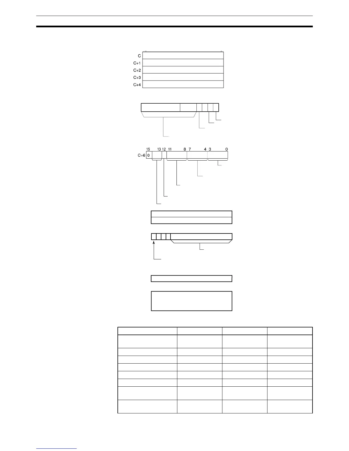
Parameters The following diagrams show the locations of the parameter data. For details
on the parameters, refer to PID Parameter Settings in this section.
Operand Specifications
15 8 07
C+5
0
32 14
PID starting integral manipulated variable
designation
Set value (SV)
Proportional band (P)
Integral constant (Tik)
Derivative constant (Tdk)
Sampling period (τ)
Forward/reverse designation
PID constant update timing designation
Manipulated variable output setting
2-PID parameter (α)
Output range
Integral and derivative unit
Input range
Manipulated variable output limit control
C+7
C+8
0
15
C+11
C+40
C+9
C+10
0
15
0
15 1214 13
000
Manipulated variable output lower limit
Manipulated variable output upper limit
Work area
(30 words: Cannot be used by user.)
AT Command Bit
AT Calculation Gain
Limit-cycle Hysteresis
Area S C D
CIO Area CIO 0000 to CIO
6143
CIO 0000 to
CIO 6105
CIO 0000 to CIO
6143
Work Area W000 to W511 W000 to W473 W000 to W511
Holding Bit Area H000 to H511 H000 to H473 H000 to H511
Auxiliary Bit Area A000 to A959 A000 to A921 A448 to A959
Timer Area T0000 to T4095 T0000 to T4057 T0000 to T4095
Counter Area C0000 to C4095 C0000 to C4057 C0000 to C4095
DM Area D00000 to
D32767
D00000 to
D32729
D00000 to
D32767
EM Area without bank E00000 to
E32767
E00000 to
E32729
E00000 to
E32767