849
Interrupt Control Instructions Section 3-20
Operand Specifications
Description MSKR(692) reads the interrupt task settings that were set with MSKS(690).
The value of N specifies the interrupt task and the kind of information that will
be read.
1. N = 0 to 3: Reading the Interrupt Mask Status of I/O Interrupt Tasks
Reads the masked/unmasked status of the interrupt inputs specified by N,
and outputs that information to the bits in D.
2. N = 6 to 13: Reading the Up/Down Differentiation of Interrupt Inputs
Reads the up/down differentiation settings of the interrupt inputs specified
by N, and outputs that information to the bits in D.
3. N = 4 or 5: Reading a Scheduled Interrupt Task’s Time Interval
C Scheduled interrupt
time units (Set in the
PLC Setup.)
Internal timer PV
10 ms 0 to 9,999 decimal (0000 to 270F hex):
Interrupt timer PV between 0 and 99,990 ms
1 ms 0 to 9,999 decimal (0000 to 270F hex):
Interrupt timer PV between 1 and 9,999 ms.
0.1 ms 0 to 9,999 decimal (0000 to 270F hex):
Interrupt timer PV between 0.0 and 999.9 ms.)
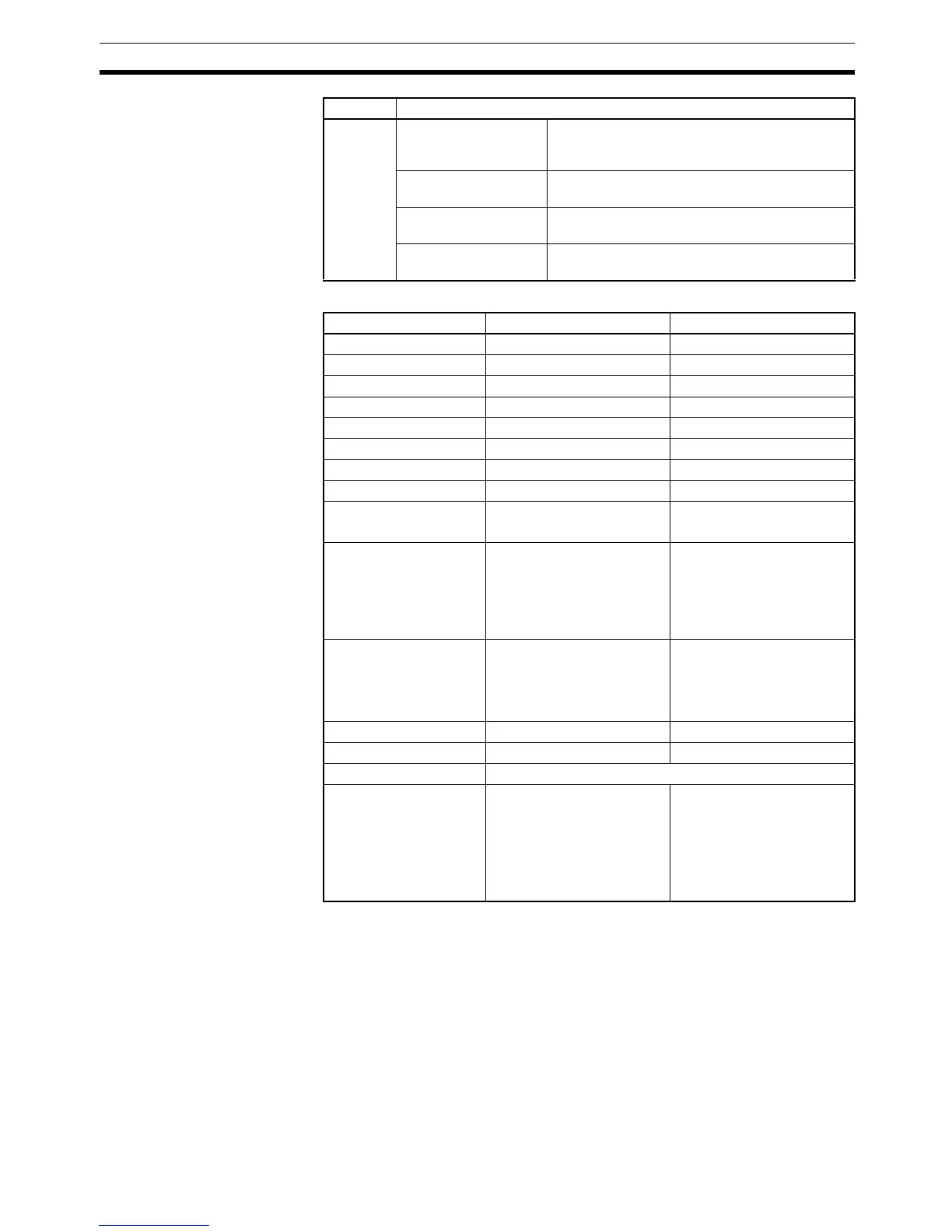
Operand Contents
Area N D
CIO Area --- CIO 0000 to CIO 6143
Work Area --- W000 to W511
Holding Bit Area --- H000 to H511
Auxiliary Bit Area --- A448 to A959
Timer Area --- T0000 to T4095
Counter Area --- C0000 to C4095
DM Area --- D00000 to D32767
EM Area without bank --- E00000 to E32767
EM Area with bank --- En_00000 to En_32767
(n = 0 to C)
Indirect DM/EM
addresses in binary
--- @ D00000 to @ D32767
@ E00000 to @ E32767
@ En_00000 to
@ En_32767
(n = 0 to C)
Indirect DM/EM
addresses in BCD
--- *D00000 to *D32767
*E00000 to *E32767
*En_00000 to *En_32767
(n = 0 to C)
Constants Specified values only ---
Data Registers --- DR0 to DR15
Index Registers ---
Indirect addressing
using Index Registers
--- ,IR0 to ,IR15
–2048 to +2047, IR0 to
–2048 to +2047, IR15
DR0 to DR15, IR0 to IR15
,IR0+(++) to ,IR15+(++)
,–(– –) IR0 to, –(– –) IR15