954
Basic I/O Unit Instructions Section 3-23
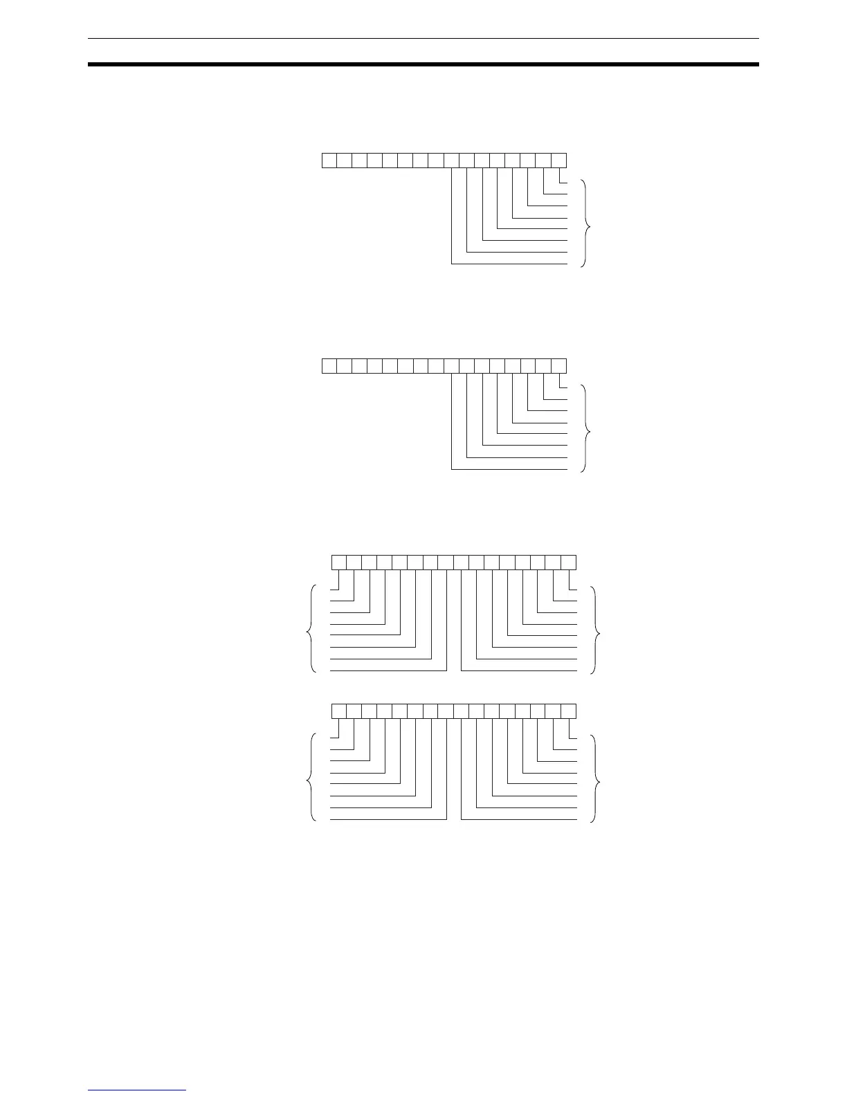
Operands I: Input Word
Specify the input word allocated to the Input Unit and connect the 8 input sig-
nal lines to the Input Unit as shown in the following diagram.
O: Output Word (Selection Signal Outputs)
Specify the output word allocated to the Output Unit and connect the 8 selec-
tion signals to the Output Unit as shown in the following diagram.
D: First Register Word
Specifies the leading word address of the 4 words that contain the data from
the 8
× 8 matrix.
0123456789101112131415
I
0
1
2
3
4
5
6
7
−−−−−−−−
Bits 00 to 07 correspond to
Input Unit inputs 0 to 7.
0123456789101112131415
O
0
1
2
3
4
5
6
7
−−−−−−−−
Bits 00 to 07 correspond to
Output Unit outputs 0 to 7.
0123456789101112131415
D
0
1
2
3
4
5
6
7
15
14
13
12
11
10
9
8
0123456789101112131415
D+1
0
1
2
3
4
5
6
7
15
14
13
12
11
10
9
8
Bits 00 to 15 correspond to
matrix elements 0 to 15.
Bits 00 to 15 correspond to
matrix elements 16 to 31.