956
Basic I/O Unit Instructions Section 3-23
Description MTR(213) outputs the selection signals to bits 00 to 07 of O, reads the data in
order from bits 00 to 07 of I, and stores the 64 bits of data in the 4 words D
through D+3. MTR(213) reads the status of the 64-bit matrix every 24 CPU
Unit cycles. The One Round Flag (bit 08 of O) is turned ON for one cycle in
every 24 cycles after each of the selection signals has been turned ON.
When executed, MTR(213) begins reading the matrix status from the begin-
ning of the matrix, regardless of the point at which the last instruction was
stopped.
There is no restriction on the number of times that MTR(213) can appear in
the program (unlike the C200HX/HG/HE and CQM1H Series).
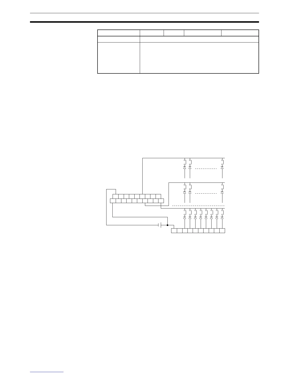
External Connections Connect the hexadecimal keypad to Input Unit contacts 0 to 3 and Output Unit
contacts 0 to 3, as shown in the following diagram.
The inputs and outputs can be connected to the following kinds of Basic I/O
Units and High-density I/O Units as long as they are not mounted in a SYS-
MAC BUS Remote I/O Rack.
• DC Input Units with 8 or more input points
• Transistor Output Units with 8 or more output points
Index Registers ---
Indirect addressing
using Index Regis-
ters
,IR0 to ,IR15
–2048 to +2047 ,IR0 to –2048 to +2047 ,IR15
DR0 to DR15, IR0 to IR15
,IR0+(++) to ,IR15+(++)
,–(– –)IR0 to, –(– –)IR15
Area I O D C
A8 A7 A6 A5 A4 A3 A2 A1 A0
A9 A8 A7 A6 A5 A4 A3 A2 A1 A0
B9 B8 B7 B6 B5 B4 B3 B2 B1 B0
OD212
ID211 I/O Unit
1
st
row
7
th
row
8
th
row